* The preview only shows a few pages of manuals at random. You can get the complete content by filling out the form below.
Description
9-1 – 9-5
MANDATORY APPENDIX 9 JACKETED VESSELS 9-1
SCOPE
9-3
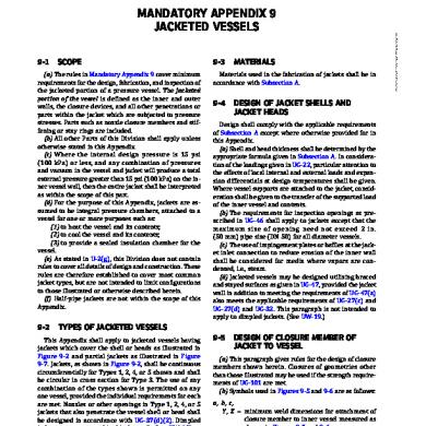
(a) The rules in Mandatory Appendix 9 cover minimum requirements for the design, fabrication, and inspection of the jacketed portion of a pressure vessel. The jacketed portion of the vessel is defined as the inner and outer walls, the closure devices, and all other penetrations or parts within the jacket which are subjected to pressure stresses. Parts such as nozzle closure members and stiffening or stay rings are included. (b) All other Parts of this Division shall apply unless otherwise stated in this Appendix. (c) Where the internal design pressure is 15 psi (100 kPa) or less, and any combination of pressures and vacuum in the vessel and jacket will produce a total external pressure greater than 15 psi (100 kPa) on the inner vessel wall, then the entire jacket shall be interpreted as within the scope of this part. (d) For the purpose of this Appendix, jackets are assumed to be integral pressure chambers, attached to a vessel for one or more purposes such as: (1) to heat the vessel and its contents; (2) to cool the vessel and its contents; (3) to provide a sealed insulation chamber for the vessel. (e) As stated in U-2(g), this Division does not contain rules to cover all details of design and construction. These rules are therefore established to cover most common jacket types, but are not intended to limit configurations to those illustrated or otherwise described herein. (f) Half‐pipe jackets are not within the scope of this Appendix.
9-2
MATERIALS
Materials used in the fabrication of jackets shall be in accordance with Subsection A.
9-4
DESIGN OF JACKET SHELLS AND JACKET HEADS
Design shall comply with the applicable requirements of Subsection A except where otherwise provided for in this Appendix. (a) Shell and head thickness shall be determined by the appropriate formula given in Subsection A. In consideration of the loadings given in UG-22, particular attention to the effects of local internal and external loads and expansion differentials at design temperatures shall be given. Where vessel supports are attached to the jacket, consideration shall be given to the transfer of the supported load of the inner vessel and contents. (b) The requirements for inspection openings as prescribed in UG-46 shall apply to jackets except that the maximum size of opening need not exceed 2 in. (50 mm) pipe size (DN 50) for all diameter vessels. (c) The use of impingement plates or baffles at the jacket inlet connection to reduce erosion of the inner wall shall be considered for media where vapors are condensed, i.e., steam. (d) Jacketed vessels may be designed utilizing braced and stayed surfaces as given in UG-47, provided the jacket wall in addition to meeting the requirements of UG-47(a) also meets the applicable requirements of UG-27(c) and UG-27(d) and UG-32. This paragraph is not intended to apply to dimpled jackets. (See UW-19.)
TYPES OF JACKETED VESSELS 9-5
This Appendix shall apply to jacketed vessels having jackets which cover the shell or heads as illustrated in Figure 9-2 and partial jackets as illustrated in Figure 9-7. Jackets, as shown in Figure 9-2, shall be continuous circumferentially for Types 1, 2, 4, or 5 shown and shall be circular in cross section for Type 3. The use of any combination of the types shown is permitted on any one vessel, provided the individual requirements for each are met. Nozzles or other openings in Type 1, 2, 4, or 5 jackets that also penetrate the vessel shell or head shall be designed in accordance with UG-37(d)(2). Dimpled jackets are not covered in this Appendix (see UW-19).
DESIGN OF CLOSURE MEMBER OF JACKET TO VESSEL
(a) This paragraph gives rules for the design of closure members shown herein. Closures of geometries other than those illustrated may be used if the strength requirements of UG-101 are met. (b) Symbols used in Figures 9-5 and 9-6 are as follows: a, b, c , Y , Z = minimum weld dimensions for attachment of closure member to inner vessel measured as shown in Figures 9-5 and 9-6
436 Copyright ASME International (BPVC) Provided by IHS under license with ASME No reproduction or networking permitted without license from IHS
Licensee=Khalda Petroleum/5986215001, User=Amer, Mohamed Not for Resale, 07/02/2019 13:29:04 MDT
--`,``,``,,`,`,,````,`,``,,,`-`-`,,`,,`,`,,`---
ASME BPVC.VIII.1-2019


