* The preview only shows a few pages of manuals at random. You can get the complete content by filling out the form below.
Description
Final Drives, Chain Drives and Tires
Introduction This unit discusses final drives, the chain drive in Motor Graders and tires. The unit begins with the theory and purpose of final drives. The operation of final drives and chain drives and ends with a short discussion on tires. Objectives At the completion of this unit, each student will be able to: demonstrate an understanding of final drives, chain drives and tires. Unit References Student Work text Tooling None Required
Unit 5: Final Drives, Chain Drives and Tires
UNIT 5
Fig. 5.1.1 Final Drive
Introduction This lesson discusses final drives. Final drives are located in wheeled machines and in tracked machines. Objectives 1. Understand the purpose of final drives. 2. Understand the operation of final drives.
Lesson 1: Final Drives
Lesson 1: Final Drives
Unit 5 Lesson 1
5-1-2
Power Train II
Fig. 5.1.2 Flow
Final Drives The final drive is the last gear reduction and helps the other power train components convert the engine speed into torque capable of pulling extremely heavy loads. In (Figure 5.1.2), the blue gears are the final drive gears.
Fig. 5.1.3 Gear Reduction
Operation The small yellow gear at the top represents the pinion from the transmission. The larger, dark yellow gear rotates slower than the small yellow pinion and the pink gear rotates even slower. The light blue gear connected to the dark blue sprocket rotates slower than any of the other gears in this group. Speed reduction equals torque increase.
Unit 5 Lesson 1
5-1-3
Power Train II
Fig. 5.1.4 Power Flow
Power Flow Power flows from the engine to the final drive through the torque converter, transmission and drive shaft.
Fig. 5.1.5 Gear Reduction With Transmission
Gear Reduction A transmission could be built large enough to accomplish the necessary speed reduction, but the drive shaft would be enormous to accommodate the tremendous twisting power of the torque from such a transmission. This would be impractical for many reasons, the main reason being the overall size.
Unit 5 Lesson 1
5-1-4
Power Train II
Fig. 5.1.6 Final Drive
Final Drive The final drives provide the torque increase in the power train. This allows the other components in the power train to carry relatively light torque loads. The result is extended service life of the power train components. The countershaft final drive (Figure 5.1.6) is sometimes called a bulltype final drive.
Fig. 5.1.7 Single Reduction Final Drive
Single Reduction Final Drive Small Track-type Tractors use a single reduction final drive. The final drive pinion drives a single, large final drive gear (brown) that is connected directly to the sprocket. There is one gear reduction, from the gold final drive pinion to the brown final drive gear.
Unit 5 Lesson 1
5-1-5
Power Train II
Fig. 5.1.8 Double Reduction Final Drive
Double Reduction Final Drive The pinion drives an idler gear (yellow) that is a cluster gear (combination of two different sized gears). The pinion that is attached to the idler gear meshes with the large (light blue) final drive gear that is connected to the sprocket. Two gear reductions take place between the input and the sprocket from the gold final drive pinion to the large gear on the yellow gear and from the pinion of the yellow gear to the light blue gear.
Fig. 5.1.9 Bull Type Final Drive
Bull Type Final Drive Final drives are reduction gearing devices. Reduction in engine speed is accomplished between each of the graduated gear sizes from the final drive pinion to the sprocket which drives the track.
Unit 5 Lesson 1
5-1-6
Power Train II
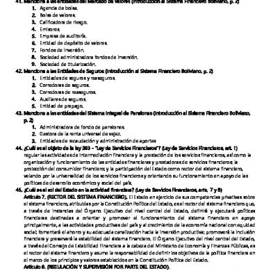
Fig. 5.1.10 Planetary Final Drive
Planetary Final Drive Planetary sets perform gear reduction and provide a maximum amount of reduction in a minimum amount of space. The sun gear is driven by the axle, the ring gear is held stationary and the carrier transfers the power.
Fig. 5.1.11 Power Flow In A Tracked Machine
Power Flow In a Tracked Machine The pinion drives the yellow gear. The sun gear drives the planet gears. The white ring gear is splined to the final drive housing and held stationary. The planet gears walk around the inside of the ring gear and force the carrier to rotate at reduced speed. The red carrier and red sprocket are splined together.
Unit 5 Lesson 1
5-1-7
Power Train II
Fig. 5.1.12 Stationary Ring Gear and Hub
Stationary Ring Gear and Hub The ring gear is mounted to a stationary hub.
Fig. 5.1.13 Power Flow In A Wheeled Machine
Power Flow In A Wheeled Machine The power comes from the axle. and drives the sun gear. The ring gear is bolted to the stationary spindle. The sun gear causes the planet gears to walk around the inside of the stationary ring gear. The carrier (yellow) is bolted to the wheel. When the planet gears walk around the inside of the ring gear and drive the carrier, the wheel assembly turns.
Unit 5 Lesson 1
5-1-8
Power Train II
Fig. 5.1.14 Stationary Ring Gear and Spindle
Stationary Ring Gear and Spindle The stationary ring gear and spindle are shown in red. A hub (red) connects the ring gear to the spindle. The spindle is bolted to the frame or axle housing. The axle and sun gear rotate within the hub and spindle. The planet gears and carrier are bolted to the wheel assembly. The wheel assembly is outlined in white.
Fig. 5.1.15 Hub and Spindle
Hub and Spindle In this view the hub, and spindle assembly on the right and ring gear on the left are splined in the center. The spindle bolts to the frame or axle housing using the mounting holes near the outer circumference and supports the wheel assembly. The teeth on the hub mesh with the ring gear teeth. All the components in (Figure 5.1.15) are stationary.
Unit 5 Lesson 1
5-1-9
FIRST REDUCTION RING GEAR
SECOND REDUCTION RING GEAR
Power Train II
SECOND REDUCTION CARRIER SECOND REDUCTION PLANETARY GEAR
FINAL DRIVE
SECOND REDUCTION SUN GEAR
FIRST REDUCTION SUN GEAR
FIRST REDUCTION CARRIER FIRST REDUCTION PLANETARY GEAR
Fig. 5.1.16 Double Reduction Final Drive
Double Reduction Final Drive The double reduction final drive has two planetary sets for two gear reductions. The axle drives the inboard sun gear. The inboard carrier walks around the ring gear. The inboard planetary carrier is splined to the outboard sun gear. The outboard sun gear rotates at the same speed as the inboard planetary carrier. The outboard planetary carrier walks around the ring gear causing the second gear reduction. The outboard planetary carrier is bolted to the wheel.
Unit 5 Lesson 1 Instructor Note
-1-
Power Train II
Unit 5: Final Drive Lab #1: Disassemble and assemble a final drive. This lab uses the same final drive that was used for the Unit 1 lab. This time, we are focusing on the final drive, not the track motor. This lab includes: • Preload adjustment for the bearings on the final drive housing. Reference Materials 311B, 312B & 312B L Excavators Machine Systems Disassembly and Assembly Module. SENR9235 Tooling Required: NOTE: Disassembly of the valve is not necessary for this lab. NOTE: Disassembly of the track motor is not necessary for this lab. NOTE: Duo-Cone seal removal is not necessary for this lab. NOTE: The balls will fall out of the bearing when the bearing cage is lifted. 138-7573 Link Bracket 1P-2420 Transmission Test Stand FT0996 Positioning Group 9U-7346 Spanner Wrench 8B-7548 Bearing Puller Assembly Press Torque Wrench Approximate Time Required: 3 hours
4 1 4 1 1
-1-
Power Train II
SPROCKET
SUN GEAR
TRAVEL MOTOR
PLANETARY CARRIER
Fig. 5.1.1 Travel Motor and Final Drive
LAB 5.1.1: TRAVEL MOTOR AND FINAL DRIVE This final drive is driven differently than the final drives we discussed. In this final drive, the ring gear and housing drives the sprocket - not the carrier. The output shaft of the travel motor is connected to the outboard sun gear in the final drive of this machine. When the motor drives the outboard sun gear, the outboard planet gears cause the outboard planetary carrier to walk around the slower ring gear. The outboard planetary carrier is splined to the inboard sun gear. When the outboard planetary carrier drives the inboard sun gear, the inboard sun gear causes the inboard planet gears to rotate on their axes. The inboard planetary carrier is connected to the motor housing and does not move. When the inboard planet gears rotate on their own axes, they drive the outer housing and ring gear at a slower speed than the inboard sun gear and in the opposite direction. The sprocket turns with the outer housing and drives the tracks. The disc for the parking brake has teeth that fit with teeth around the barrel. When oil pushes the parking brake piston back, the parking brake will be released. The barrel will rotate freely. When oil is not present, the springs will push the parking brake piston into the parking brake disc. The barrel will be held by friction and will not rotate.
Lab 5.1.1 Final Drive
Unit 5 Lab 5.1.1
Unit 5 Lab 5.1.1
-2-
Power Train II
LAB 5.1.1: TRAVEL MOTOR AND FINAL DRIVE
Correction to SENR9235 - Step 51 a. Tighten ring nut to 9.8 Nm (7.25 lb ft) b. Using 8B-7548, 2 bolts, a socket and a torque wrench, rotate the ring gear. Measure the rotational torque of the ring gear. Record this torque.
c. Add 21.4 Nm (15.8 lb ft) to the recorded torque.
d. Tighten the ring nut until the rotational torque of the ring gear reaches the torque found in step c.
-3-
Power Train II
LAB 5.1.1: TRAVEL MOTOR AND FINAL DRIVE
Reference: Use 311B Excavator Disassembly & Assembly Hydraulic System “Disassemble and Assemble Travel Motors and Final Drives
1. Mount the final drive on the transmission stand 2. Are the shafts in the planetary gears pressed on? No 3. Which component used to be connected to the shaft from the travel motor? The shaft with the outer sun gear on it. 4. How is the first planetary set connected to the second planetary set? The sun gear on the inner planetary and the carrier on the outer planetary. 5. What important tool is missing from Step 37 and from the “Tools Needed” list? The spanner to remove the ring nut - 9U7346. 6. Which component of the Duo-Cone seal in Step 41 is doing the sealing? The metal rings. Assembly 1. When doing Step 45 and Step 47, what do you have to make sure of? Do not twist - push in evenly on all sides. 2. When you torque the ring gear in Step 51, does it continue to rotate? Yes 3. Why is this adjustment important? The ring gear moves with the sprocket - which drives the tracks.
SENR9235
Instructor Copy: Lab 5.1.1 Final Drive
Unit 5 Instructor Copy Lab 5.1.1
-4-
Power Train II
LAB 5.1.1: TRAVEL MOTOR AND FINAL DRIVE Name__________________________ Reference: Use 311B Excavator Disassembly & Assembly Hydraulic System “Disassemble and Assemble Travel Motors and Final Drives
1. Mount the final drive on the transmission stand 2. Are the shafts in the planetary gears pressed on?
3. Which component used to be connected to the shaft from the travel motor?
4. How is the first planetary set connected to the second planetary set?
5. What important tool is missing from Step 37 and from the “Tools Needed” list?
6. Which component of the Duo-Cone seal in Step 41 is doing the sealing?
Assembly 1. When doing Step 45 and Step 47, what do you have to make sure of?
2. When you torque the ring gear in Step 51, does it continue to rotate?
3. Why is this adjustment important?
SENR9235
Student Copy: Lab 5.1.1: Final Drive
Unit 5 Student Copy Lab 5.1.1
-1-
Power Train II
POWER TRAIN 2
1. What is the purpose of the final drive? The last gear reduction in the power train - more torque to take the load. 2. What are the two main types of final drives? Counter shaft or bull type, planetary. 3. Describe what we mean by single reduction and double reduction. Single reduction has one gear reduction between the input and the output. Double reduction has two gear reductions between the input and the output. 4. Match the state of the components in a planetary final drive. b c a
Sun gear Ring gear Planetary carrier
a. This component drives the wheel or the sprocket. b. Input power drives this component. c This component remains stationary.
Instructor Copy: Quiz 5.1.1
Unit 5 Instructor Copy Quiz 5.1.1
-1-
Power Train II
POWER TRAIN 2 Name________________________________ 1. What is the purpose of the final drive?
2. What are the two main types of final drives?
3. Describe what we mean by single reduction and double reduction.
4. Match the state of the components in a planetary final drive. _______ Sun gear _______ Ring gear _______ Planetary carrier a. This component drives the wheel or the sprocket. b. Input power drives this component. c. This component remains stationary.
Student Copy: Quiz 5.1.1
Unit 5 Student Copy Quiz 5.1.1