Review
Piezoelectric Inertia Motors—A Critical Review of History, Concepts, Design, Applications, and Perspectives Matthias Hunstig Grube 14, 33098 Paderborn, Germany;
[email protected] Academic Editor: Delbert Tesar Received: 26 November 2016; Accepted: 18 January 2017; Published: 6 February 2017
Abstract: Piezoelectric inertia motors—also known as stick-slip motors or (smooth) impact drives—use the inertia of a body to drive it in small steps by means of an uninterrupted friction contact. In addition to the typical advantages of piezoelectric motors, they are especially suited for miniaturisation due to their simple structure and inherent fine-positioning capability. Originally developed for positioning in microscopy in the 1980s, they have nowadays also found application in mass-produced consumer goods. Recent research results are likely to enable more applications of piezoelectric inertia motors in the future. This contribution gives a critical overview of their historical development, functional principles, and related terminology. The most relevant aspects regarding their design—i.e., friction contact, solid state actuator, and electrical excitation—are discussed, including aspects of control and simulation. The article closes with an outlook on possible future developments and research perspectives. Keywords: inertia motor; stick-slip motor; smooth impact drive; piezeoelectric motor; review
1. Introduction Piezoelectric actuators have long been used in diverse applications, especially because of their short response time and high resolution. The major drawback of these solid state actuators in positioning applications is their small stroke: actuators made of state-of-the-art lead zirconate titanate (PZT) ceramics only reach strains up to 2h. A typical piezoelectric actuator with 10 mm length thus reaches a maximum stroke of only 20 µm. Bending actuator designs [1] and other mechanisms [2] can increase the stroke at the expense of stiffness and actuation force ([3]; [4] (pp. 287–289)), but strokes of a few millimetres are hard to reach, even with such structures. In piezoelectric motors, these small strokes are repeated at frequencies of of up to several 100 kHz and are accumulated using different principles to achieve a macroscopic movement. This movement can be linear or rotary, and is principally unlimited. Orbital or spherical trajectories are relatively simple to realise. Compared to typical electromagnetic motors, piezoelectric motors provide large force or torque at small size, powerless holding-force, magnetic insensitivity, and are well-suited for miniaturisation [5,6]. Since the invention of the first piezoelectric motors in the 1940s [7], numerous piezoelectric motors have been developed and described in literature. Nowadays, it is difficult to keep track of the ever-growing variety of piezoelectric motors. This contribution does not aim to provide a general review or classification of piezoelectric motors, as many authors have done so before, e.g., [8]; [9] (pp. 27–33); [10]; [11] (p. 32); [12] (p. 414); [13] (p. 5); [14]; [15] (p. 9); [16–18]. The proposed classification schemas differ, and none of them comprises all motor variants described in literature. For this reason, there is no generally accepted detailed classification of piezoelectric motors. However, up to four common groups are usually recognised: Actuators 2017, 6, 7; doi:10.3390/act6010007
www.mdpi.com/journal/actuators
Actuators 2017, 6, 7
• • • •
2 of 35
Standing wave motors Travelling wave motors Walking piezoelectric motors Inertia motors
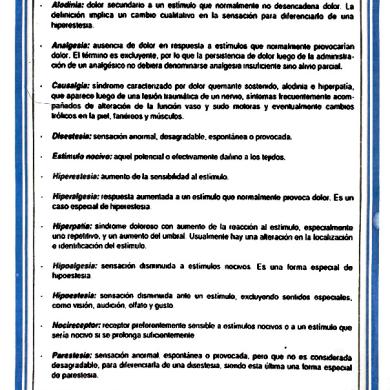
Standing wave and travelling wave motors are the oldest and best known piezoelectric motors. They are often summarised under the terms “ultrasonic motors” or “resonant motors” because resonant vibration of the stator at ultrasonic frequencies is usually used to obtain the desired vibration amplitude of contact points on the stator. These contact points drive the rotor through a friction contact. Walking piezoelectric motors operate below their resonance frequency, and follow the “clamp and feed” principle. One piezoelectric actuator is used to clamp the rotor, while another actuator moves it. This contribution does not go into detail on these three motor types, but focuses on a detailed overview and critical review of the fourth group: piezoelectric inertia motors. These motors are often inferior to other piezoelectic motors in terms of force, velocity, or power. However, they have a simple mechanical design, are typically controlled by only one electrical signal per degree of freedom, and inherently provide a fine positioning capability with principally unlimited resolution. These characteristics are additional advantages for miniaturisation, and make inertia motors suitable for use in mobile phone cameras, cp., for example [19–25]. All of their many variants make use of the inertia of the driven part to drive it through an uninterrupted friction contact. The functional principle of two basic inertia motor designs is illustrated in Figure 1. These motors are also known as “stick-slip motors” because of the repeated transition between static and sliding friction that is present in many inertia motors. Figure 2 shows five piezoelectric inertia motors from the literature, illustrating the large variety of motor designs.
m1
actuator
m2 slow expansion, m2 sticks
m actuator
rod
m actuator
m1
actuator
m2 sudden stop, “impact” from m2, m1 slides
rod
m actuator
slow expansion, stiction fast contraction, sliding
m1
m2
actuator
fast contraction, m1 slides
rod m1
(a)
actuator
m2
(b)
Figure 1. Schematic representation of the two basic designs of inertia motors and their functioning in classic “stick-slip” operation, including typical excitation signals. (a) Fixed actuator type; (b) Moving actuator type.
Actuators 2017, 6, 7
3 of 35
(a)
Pipe
(b)
Mass Springs Bending Actuators
(c)
(d)
(e) Figure 2. Some inertia motors from the literature, using different piezoelectric actuators and different mechanisms to generate normal force. (a) Fixed actuator motor with one linear axis using a piezoelectric stack actuator and a metal spring to generate normal force (Reprinted from [26] with permission from Wiley); (b) Fixed actuator motor with one linear axis using a piezoelectric bending actuator (two piezoelectric discs glued to a passive central disc) and a rubber spring to generate normal force (Reprinted from [27], Copyright 2006 The Japan Society of Applied Physics); (c) Moving actuator motor for linear movement inside pipes (cross-section), using three piezeoeletric bending actuators and flat metal springs to generate normal force (as described in [28,29]); (d) Fixed actuator spherical motor with three rotational axes using piezoelectric shear actuators and a magnet (M) to generate normal force (Reprinted from [30] with the permission of AIP Publishing); (e) Schematic (left) and prototype (right) of a fixed actuator motor for resonant operation with one rotational axis, using a monolithic piezoelectric actuator and a helical spring to generate normal force (Reprinted with permission from [31]).
Actuators 2017, 6, 7
4 of 35
Zhang et al. [32] published a first review on piezoelectric inertia motors in 2012. Their contribution gives a broad overview of motors described in the literature, describes the structure and functional principle of different motors in detail, and lists some performance data. However, some of the explanations and discussions are rather brief, and some aspects and recent developments—especially regarding inertia motors operating at high frequencies and/or without phases of stiction—are not covered. So, this contribution can be seen as a complement to the review by Zhang et al. [32] on some aspects of piezoelectric inertia motors, offers an alternative view on some other aspects, and discusses several topics not included in the previous review. With this aim, Section 2 discusses the historical development of piezoelectric inertia motors and their applications in positioning and force generation. In Section 3, the basic functional principles of fixed and moving actuator inertia motors are explained in detail. This includes a definition of four modes of operation, two of which use sliding friction (and not stiction) for generating propulsion. Based on these concepts, the different terms used in literature to describe this type of motor are discussed, and a general definition is proposed in Section 4. Section 5 takes a closer look at the most relevant aspects regarding the design of inertia motors. The friction contact, the solid state actuator, and the electrical excitation are each discussed in detail; this includes aspects of control and simulation. Section 6 closes the article with a summary and an outlook on possible future developments and research perspectives. 2. History and Application Review 2.1. First Developments The invention of piezoelectric inertia motors is commonly attributed to Pohl [33,34] or Higuchi et al. [35]. Anders et al. [36] should be mentioned on par with these two. They presented their work [36] in July 1986 at the same conference as Pohl [33] (First International Conference on Scanning Tunneling Microscopy (STM’86) in Santiago de Compostela, Spain, 14–18 July 1986; Volume 181 of “Surface Science” contains the proceedings of this conference, which include [33,36]), and submitted and published a paper at almost the same time as him. However, their paper was met with far smaller response than Pohl’s. In a work published in 1984 [37], Higuchi described electromechanical micropositioning devices. In a work published in 1987 [35], he transferred their functional principle to piezoelectrically-actuated mechanisms, so these devices can be regarded as predecessors of piezoelectric inertia motors. In fact, Söderquist already described devices for fine positioning using electromagnetic and piezoelectric actuators in 1973 in a Swedish patent [38]. These devices resemble the electromagnetic motors proposed by Higuchi [35,37]. They are not inertia motors according to the above definition, but impulsive manipulators [39]. Yet, they can be regarded as the first predecessedors of today’s inertia motors, even though it is unlikely that Söderquist’s patents were known to the later inertia motor developers. 2.2. Positioning Applications The first piezeoelectric inertia motors were developed for horizontal positioning (e.g., in microscopy). In the years following the above-mentioned first publications, several researchers developed inertia motors in a multitude of designs. Practically all of these developments focused on microscopy applications, many related to the then-new scanning tunnelling microscopes and other scanning probe microscopes [40–47]. Many developments were not intended for industrial production, but for use in the developers’ own laboratories. Reported improvements of motor designs mostly concerned the maximum slope a motor could handle—using mechanisms to generate a gravity-independent normal force, vertical motion was soon achieved [44,48–50]—and the integration of multiple degrees of freedom into one device [30,42,49–52]. Since 1990, the number of publications regarding inertia motors has continuously increased. (A search on Google Scholar and Scopus on
Actuators 2017, 6, 7
5 of 35
12 February 2013 showed that the number of publications regarding piezoelectric inertia motors increased by a factor of about 30 between 1987 and 2012). Positioning in laboratory applications like microscopy [53], cell manipulation [54–56], and micro or nano handling [57–61] is still a main area of application for piezoelectric inertia motors today. Many companies have specialised in fabricating precision inertia motors for such applications. Figure 3 presents a survey of the maximum velocities and forces of commercially available inertia motors. Depending on the design, actuation forces up to 22 N or velocites up to 70 mm/s are obtained, but most motors reach less than 10 N and 20 mm/s. Especially the velocity is low compared to other types of piezoelectric motors (cp. e.g., [14]). attocube ANPz30 attocube ANPx51, ANPz51, ANPz51eXT attocube ANPx101, ANPx311, ANPx321, ANPx341 attocube ANPz101, ANPz102, ANPz101eXT12 attocube ECSx3030 to ECSx3080 attocube ECSx3050/HL to ECSx3080/HL attocube ECSxy5050 attocube ECSz5050 Cedrat LSPA30uXS Cedrat LSPA35XS, LSPS35XS Cedrat LSPS40SM imina miBot BT-14 Kleindiek MM3A-EM 2 Klocke Nanomotor S Klocke Nanomotor L Klocke Nanomotor B mechOnics ML17 2 mechOnics MS15 2 mechOnics MS30, DS30, DS40 2 mechOnics MS38, NDS40 2 mechOnics NDS70 2 mechOnics DSP50 2,3 New Focus picomotor 8301NF, 8302, 8303, 8321, 8322NF, 8341NF New Focus picomotor 8353, 8354 PiezoTech TULA35 PiezoTech TULA50 PiezoTech TULA70 PiezoTech XDT50-045H 3 PI N-412, N-422 PI N-470, N-472 PI Q-521, Q-522 PI Q-545 Sensapex Single Axis Micromanipulator 1 SmarAct SLC-17, SLC-24, SLL12, SLLA42, SLLV42 SmarAct SLC-17-D, SLC-24-D SmarAct SHL-20N-10 SmarAct SL-06 Xidex Nanobot NX 1
1
maximum actuation force / N
10
0
10
−1
10
−2
10
10
−1
0
10 maximum velocity / mm/s
1
10
1 2 3
no force value available holding force, actuation force not available incorporates multiple inertia motors per DOF
Figure 3. Maximum actuation force and velocity of commercially available translatory inertia motors. All are driven piezoelectrically, and apart from the imina miBot, all are fixed actuator motors. The Appendix A contains a list of companies.
Higuchi et al. [62] were the first to use inertia motors in a micro robot in 1990, and Saito and Nagano [63] described imaging applications in 1991. However, only in the late 1990s did the number of publications on non-microscopy applications of inertia motors began to grow significantly. Actual or intended positioning applications of inertia motors can be differentiated into two groups. This differentiation is often helpful when comparing inertia motors, as the desired motor characteristics differ significantly. In one group of applications, high precision is of the highest priority; these applications will be called precision applications in the following sections. On the other hand, velocity applications prioritise high velocity and often low cost over precision. Application-oriented literature was focused on precision applications like micropositioning and microrobotics in the first years [57,64–67], and is nowadays dominated by velocity applications in miniaturised consumer goods [68], like zoom and autofocus mechanisms for miniaturised digital cameras as used in mobile phones [19–25]. Other investigated applications include braille cells [69] and discharge machining [70]. In commercial mass products, inertia motors provide zoom, focussing, and image stabilisation in digital cameras, for example by Sony [71], formerly Konica Minolta ([20]; [72] (p. 650203-7f)).
Actuators 2017, 6, 7
6 of 35
An inertia motor with a single fixed actuator can also move multiple objects, ranging from two masses—which can be moved independently by varying the driving signal [25]—to large numbers of microscopic particles [58]. To date, these remain niche concepts. 2.3. Force Generation As the above survey shows, piezoelectric inertia motors are almost exclusively used in positioning applications with little to no force. Even in these applications, it is generally advantageous if a motor can provide a certain force, as this implies a certain robustness against disturbances such as wear and dirt. It also allows non-horizontal operation and fine-positioning applications where flexure hinges exert a small restoring force. Additionally, some of the positioning applications described above—such as cell manipulation [54–56] and micro or nano handling [57–61]—require a certain, yet usually low, force. One of the few examples where a larger force exerted by an inertia motor is used in an application is the indentation device developed by Rabe [73]. The force generated by an inertia motor has been investigated in only a few publications. It has been measured using different methods: making the slider move against a spring, the force is either determined from the deformation of the spring [61,74,75], or using a load cell connected to the spring [76,77]. Other authors make the slider move directly against a load cell [67,78–81], or the force is exerted to a part connected to a load cell instead of a slider [82]. (Bergander et al. [67] (p. 33) and Kang et al. [78] (p. 610) only state that they measured the force of the slider “with a precision balance” respectively “using a digital power gauge”. It is likely that this was done with direct contact between slider and measurement instrument.) Another option is to make the motor lift weights [83–85]. The force generation potential can also be estimated from the transient motor behaviour [86]. To what degree forces determined using these different methods with differing parameters can be compared has yet to be investigated. Recently, it has been shown that running the slider against a spring is a robust method of determining the force generation potential of an inertia motor, providing results independent of the spring stiffness as long it is sufficiently low ([87] (pp. 73–77), in short form also [77] (p. 7)). This method is also suited for non-iterative numerical simulation [87] (pp. 73–77). It thus appears as an advantageous measurement method for comparing the force generation performance of different inertia motors. Controlled force generation with inertia motors has been investigated by Edeler et al. [79,88,89]. These works have shown that in the investigated motor, the generated force—determined using the spring method—depends on a number of parameters, such as slider mass, friction contact, pre-load, and excitation signal. An influence of the excitation signal on the generated force was also demonstrated for an inertia motor with a very different concept by Hunstig et al. [77,87]. Edeler and Fatikow [79] experimentally demonstrated for their motor that up to a maximum friction force, the producible force is approximately proportional to the friction force. This relationship was also shown theoretically for horizontally-acting high-frequency inertia motors by the author [87] (p. 92f). 3. Basic Functional Principles All known realisations of piezoelectric inertia motors can be reduced to one of two basic designs. These are shown in Figure 1 with one linear degree of freedom (DOF) to explain their functional principle. The fundamental difference is whether the solid state actuator driving the motor is part of the fixed (“fixed actuator type”) or of the moving part of the motor (“moving actuator type”). A motor with multiple DOF can combine both types; for example, create linear motion with a fixed actuator, and rotation with a moving actuator [90]. Zhang et al. [32] additionally differentiate two types of “moving actuator” motor, based on which part of the motor (m1 or m2 in Figure 1b) is regarded as the object to be moved.
Actuators 2017, 6, 7
7 of 35
3.1. Fixed Actuator Type Figure 1a shows the functioning of an inertia motor with fixed actuator and one translatory DOF in a simplified diagram with one phase of static friction and one phase of sliding friction. In the first 1 → 2 , the driving rod is moved with low acceleration in one direction. step, the propulsion phase The mass m sticks to the rod, and is carried along because its inertial force is lower than the break-away force µ0 FN , calculated from the coefficient of static friction µ0 and the normal contact force FN . In the 2 → 3 , the driving rod is moved back with high acceleration. second step, the retraction phase The force required to carry the mass along is larger than the break-away force—the mass breaks loose and slides on the rod. If the retraction phase directly follows the propulsion phase, the mass continues to slide to the right due to its kinetic energy, while the rod returns to its starting position. If the mass is at rest before the retraction phase begins, it is moved to the left by the friction force, but this backward movement is smaller than the forward movement during the propulsion phase. The result is an aggregate displacement of the mass, which can be arbitrarily multiplied by repeating the cycle described above. The first examples for such motors and the concept of their movement cycle consisting of alternating phases of static and sliding friction (“stick-slip”) are the motors by Anders et al. [36] and Pohl [34]. 3.2. Moving Actuator Type In inertia motors with moving actuator as shown in Figure 1b, a mass is attached to either side of the actuator. One of these masses is in contact with the underground and, through this contact, provides displacement of the whole motor. The functional principle of such a motor is shown in 1 → 2 ) and a sliding phase of Figure 1b in a simplified form, with a stiction phase of slow extension ( 3 → 4 ). If the extension is sufficiently fast, the sudden stop at its end ( 2 → 3 ) quick contraction ( can be utilised to generate additional displacement: the force required to instantly stop m2 is larger than the break-away force; thus, m1 breaks loose and the motor slides until its kinetic energy is dissipated in the friction contact. The total displacement per cycle is thus composed of up to two distinguishable steps. The first example of an inertia motor with moving actuator and the concept of its movement cycle was presented by Higuchi et al. [35]. Fixed and moving actuator motors share the advantages of inertia motors described in Section 1. Table 1 additionally lists some of their individual pros and cons. The main advantage of moving actuator motors is their “unlimited” displacement, while fixed actuator motors can generally be smaller and faster. Table 1. Pros (+) and cons (−) of fixed and moving actuator inertia motors. Fixed Actuator Inertia Motors + can use the kinetic energy of the slider for additional movement during/after retraction of the slider (relevant mostly in high-frequency operation)
+ moving mass m can be very small, and has no effect on the frequency characteristics of the stator + higher possible operation frequencies, thus higher possible velocities − displacement limited by the length of the rod Moving Actuator Inertia Motors + additional motion can be generated by the ”impact” of the mass m2 (relevant mostly in low-frequency operation)
+ does not require fixation + displacement limited only by the surface it operates on and by the wiring − requires a proper, well machined surface to operate reliably − mass m2 must be relatively large; this makes the motor heavy and limits excitation frequency and maximum velocity
Actuators 2017, 6, 7
8 of 35
3.3. Modes of Operation
t
t
t
t
∆t2
∆t2
x ¨S
∆t1
∆t2
t
t
t
t
t
∆t1
∆t1
x ¨S
(d) x ¨R
(c)
∆t1
x˙ S
x˙ R
x˙ S t
∆t1
t
t
x ¨S
t
∆t1
xS
xS
xR x˙ R
∆t2
t
t
x ¨R
∆t1
∆t2
x ¨R
t
(b) ∆t1
xR
x ¨S
x ¨R
(a)
t
t
x˙ S
x˙ R
t
x˙ S
x˙ R
t
xS
xR
xS
xR
In a theoretical investigation of the idealised operation of inertia motors [91], four principally different modes of operation of fixed actuator inertia motors have been previously identified. Figure 4 shows the displacements and velocities of rod and slider of a motor as in Figure 1a driven with a parabolic sawtooth signal in these four modes of operation. They differ by two criteria: does the slider move in discrete steps or continuously, and is the propulsion of the slider achieved using stiction or by sliding friction only? The motor velocity in stick-slip operation or with discrete steps (Figure 4a–c) is limited principally, only continuous slip-slip operation (Figure 4d) allows very high velocities [91]. This is also true for real inertia motors which operate with multiple phases of stiction and sliding per cycle [92]. A drawback of slip-slip operation is that wear—which is influenced significantly by the applied excitation signal [92]—is generally higher than in stick-slip operation using similar excitation signals due to the increased sliding distance.
∆t1
∆t1
∆t1
∆t1
˙ of rod (index R ) and slider (index S ) of a fixed Figure 4. Simulated displacement (x) and velocity (x) ∆t ∆t ∆t ∆t actuator motor as in Figure 1a over time t in four modes of operation. All scales of the ∆tsame type (time, t t t t displacement, velocity) are equal in all diagrams. (Diagrams from [91], reprinted with permission from Elsevier). (a) Discrete stick-slip operation: slider driven by stiction, at rest after each step; (b) Continuous stick-slip operation: slider driven by stiction, moves continuously; (c) Discrete slip-slip operation: slider driven by sliding friction, at rest after each step; (d) Continuous slip-slip operation: slider driven by sliding friction, moves continuously. 2
2,2
2
2,3
2,4
It is sometimes claimed in the literature that the coefficients of static and dynamic friction must be different for an inertia motor of either type to function (e.g., in [93] (p. 187)). It becomes clear that this is not necessary by taking a closer look at the slider movement in stick-slip operation (Figure 4a,b): in a horizontally operating motor as in Figure 1a, the maximum gradient of the rising flank (positive acceleration) of the slider velocity x˙ S is a0,max = µ0 Fc /mS ,
(1)
where µ0 is the coefficient of static friction (stiction), Fc is the normal force in the contact between slider and rod, and mS is the mass of the slider. The gradient of the falling flank (negative acceleration) is
Actuators 2017, 6, 7
9 of 35
a− d = − µd Fc /mS ,
(2)
where µd is the coefficient of dynamic (sliding) friction. A velocity profile as in Figure 4a,b—where the average of x˙ S over time is positive and the slider thus moves into the desired direction—can be achieved with almost any ratio of a0,max and ad . The rising flank does not have to be steeper than the falling flank; i.e., µ0 does not have to be larger than µd . However, situations with µ0 < µd are very rare, can only occur with non-constant friction coefficients, and are not relevant in the practical applications of inertia motors. Thus, µ0 ≥ µd is a valid assumption. The same rationale can be applied to the ”slip-slip” mode of operation (Figure 4c,d): if the acceleration of the driving rod is sufficiently high in the propulsion phase, the mass also slides in this phase, with the acceleration a+ (3) d = µd Fc /mS . Equations (2) and (3) show that the acceleration of the mass is of equal magnitude in both directions, assuming constant µd and Fc . In continuous slip-slip operation, the mass is nevertheless accelerated over the first cycles, because with appropriate asymmetric driving signals, the opposing friction forces act for different lengths of time until the motor reaches its steady state, cp. Figure 4d. Such continuous slip-slip operation has been realised and described a few times [25,26,86,91,94] for fixed actuator motors. Slip-slip operation is also possible in moving actuator motors, but has not been demonstrated in the literature to date. It must be noted that the actual movement cycle in an inertia motor of either type in any mode of operation can consist of a multitude of phases of static or sliding friction. It can thus be much more complex than in the principle explanations above. The macroscopic stationary velocity v¯ ∞ of an inertia motor with a constant driving signal can be calculated as the product of its step size x¯ ∞ ; i.e., the displacement per cycle (typically ranging from several nanometres to some 10 µm) and its operation frequency f 1 (typically between 100 Hz and several 100 kHz): v¯ ∞ = x¯ ∞ · f 1 (4) Published velocities of inertia motors range from well below 1 mm·s−1 (especially in early setups for precise positioning [34,35,44]) to well over 100 mm·s−1 in current high-frequency motors, with the maximum of 750 mm·s−1 achieved by Nishimura and Morita [95]. It should be noted that the step size depends on the driving signal, and as such, can vary substantially in one motor. In particular, high-frequency motors operating in “slip-slip” mode in continuous operation show a very different step size when driven with only a single driving pulse (cp. Figure 4d), and in some motors, the step size can be modified to vary the velocity (cp. Section 5.3.4). In the “stepping mode” described above, inertia motors can produce unlimited displacements (at least in principle), with a positioning resolution equal to the step size. The design of both types of piezoelectric inertia motors allows a second mode of operation often called “scanning mode” [67,96–99]. In this mode, the object to be moved (m in Figure 1a, m2 in Figure 1b) is displaced by applying a DC voltage to the piezoelectric actuator. The resolution in this mode is typically below 1 nm [4,99–101], limited only by the resolution of the driving electronics. The stepping mode is an essential feature in many precision applications of inertia motors (cp. Section 2.2), while velocity applications mostly do not use the stepping mode. Combination of stepping and scanning operation into one controller has been demonstrated by Claeyssen et al. [84]. 4. Terminology and Proposed General Definition As discussed in the above sections, numerous variants of piezoelectric motors exist. In the case of piezoelectric inertia motors, ambiguity starts with inconsistent naming in the literature. The movement cycle consisting of stick and slip phases as shown in Figure 1 has sparked terms like “stick-slip mechanism”, “drive”, “actuator”, or “motor” [41,51,97,102–107], which are mostly
Actuators 2017, 6, 7
10 of 35
used for fixed actuator motors. However, these terms are not always appropriate, and also not unambiguous. Firstly, if forward and backward movement of the actuator are sufficiently fast or superposed by high-frequency oscillations, there is no stable phase of stiction. Secondly, there are motors (e.g., the nanopositioner by Voigtländer et al. [108] or the “stick-and-clamp” mechanism by Lee et al. [109]) which use alternating phases of stiction and sliding for propulsion, but not the inertia of the driven object. “Impact drive” is a common denomination for inertia motors with a moving actuator. This term was coined by Higuchi et al. [110], who for the first time used the fast stopping of a mass, which has an effect on a connected second mass (cp. Figure 1b) similar to an impact, to generate displacement in their moving actuator inertia motors [35]. Okamoto and Yoshida [26] picked up this term for their fixed actuator inertia motor, and expanded it to “smooth impact drive mechanism” (SIDM), a term also used later by other authors. “Stick-slip drive” and “impact drive” are also occasionally used to differentiate inertia motors with fixed actuator from those with moving actuator ([111] (p. 36f); [112]). This differentiation seems justified, as only moving actuator inertia motors can use an “impact” on the motor to generate additional displacement, but this explanation is rarely found in literature [111] (p. 37f). The use of the different terms rather seems to have historical reasons: “impact drive (mechanism)” is used for moving actuator motors, and mostly by authors whose works are to different extents based on the early works of Higuchi et al. [35,110] on this type of motor; e.g., in [64,70,113–116]. The derived term “smooth impact drive mechanism” is used for fixed actuator motors by authors who directly or indirectly refer to the works of Okamoto, Yoshida et al. [26,117,118] (e.g., in [25,95,119,120]). On the other hand, “stick-slip drive” or similar has been used for inertia motors of any design, even if they clearly have a moving actuator; e.g., the motors of Niedermann et al. [41] and Smith et al. [51]. Zesch [65] differentiates inertia motors based on the ratio of the two moving masses. Referring to a schematic like Figure 1b, he writes: “In its general form—both m1 and m2 are non-zero—the inertial drive is known as Impact Drive [...] The setup, when m1 decreases towards zero, is often called Stick-Slip Drive” [65] (p. 36). This differentiation is also found in the works of Breguet [66] (p. 12) and Driesen [121] (p. 56). In fact, m1 and m2 are of similar magnitude in most moving actuator motors, and the dynamics of fixed actuator motors can be improved by reducing the mass of the driving rod. However, a low mass m1 is also beneficial for moving actuator motors, and a fixed actuator motor can—albeit with worse dynamics—also work with equal masses of driving rod and payload. It is thus questionable whether such a differentiation is meaningful. One essential feature of this type of motor is independent from the design and the employed type of actuator: using the inertia of a mass to drive this mass through a friction contact with permanent or intermittent sliding. Many authors thus describe these motors as “inertial slider”, “inertial sliding drive”, “inertia slip drive”, “friction-inertia actuator”, or similar [32,42–44,47,49,122–128], also as a comprehensive term when differentiating between “stick-slip drive” and “inertial drive” [65,111,121]. Zhang et al. [32] (p. 674) criticise short terms like “inertia motor” as misleading, because they omit the friction necessary for the motor to function. (Sliding) friction is indeed essential in these motors. However, as it also occurs in other technically relevant piezoelectric motors (cp. e.g., [13,129,130]), it is not a suitable differentiating feature. So, in the search for a descriptive yet concise name for this type of motor, “inertia motor” appears to be the best candidate. It is thus used throughout this publication. This and similar terms are also occasionally used for (fictional) motors creating propulsion without repulsion, thus violating Newton’s third law of motion—“actio est reactio”. Such motors are found in science fiction, but have also been and still are being developed [131] and applied for a patent, for example by Davis [132] and Lasch [133]. As their supposed functional principle obviously violates fundamental physical laws, there are only a few critical discussions of such motors in the literature, like those by Adams [134] and Millis and Thomas [131]. It should be noted that also driving a body by using its inertia is not exclusive to inertia motors, but for example is also done in vibratory conveyors [135].
Actuators 2017, 6, 7
11 of 35
This discussion of terminology gives an indication of the diversity of inertia motors and of the difficulty of finding a clear yet comprehensive definition of this type of motor. The following general definition of an inertia motor has been proposed earlier by the author [87] (p. 9). It is based on studying more than 300 publications, and covers a wide range of motors with very different designs and for very different applications. It is formulated for a motor with one translatory DOF, but is just as valid for rotatory motors and motors with multiple DOF: In an inertia motor, an actuator of limited stroke, acting essentially parallel to the motor axis, drives an object through an uninterrupted contact. The object can travel a distance larger than the actuator stroke. The inertia of the object is essential for its movement. How any specific motor should be categorised is determined by its construction and by its electrical control. For example, the inertia motor stepping mode (cp. Section 3.3) is used as an alternative operating mode in several motors with a different preferred mode of operation ([108] (p. 10); [136]; [137] (p. 24)). Additionally, inertia motors with quickly changing normal force can operate like standing wave motors (cp. Section 5.1.1). 5. Design Aspects The basic construction of inertia motors is simple: they consist of few parts which are easy to manufacture and are generally controlled by a single electrical signal per DOF. (In resonant motors like the one described by Tuncdemir et al. [138]—where different modes of vibration can be excited by varying the excitation signal—it is possible to (sequentially) use multiple DOF with only one electrical input.) In its simplest form, an inertia motor with one DOF as in Figure 1a consists of three parts: a solid state actuator and a driving rod, forming the stator of the motor, and a slider moving along the rod. The friction contact between rod and slider, the solid state actuator, and the electrical excitation are the most important aspects in the design of an inertia motor, and shall be reviewed in the following. 5.1. Friction Contact Figure 5 shows a rigid body model of a simple translational inertia motor, which will be used in the following discussion of the friction contact: a slider of mass mS hangs below the driving rod. x R (t) and xS (t) are the displacements of the rod and slider, respectively. The contact force Fc (t) between rod and slider results from the gravitational force Fg and an external force Fz (t), both acting on the center of gravity C of the slider. The friction force Ff (t) acts between rod and slider. This contact has a tangential stiffness k t .
Figure 5. Rigid body model of a simple translational inertia motor.
Actuators 2017, 6, 7
12 of 35
5.1.1. Generation and Variation of Normal Force In inertia motors operating horizontally or with small angles of inclination, the weight of the slider can produce sufficient contact force Fc (t) if the slider is placed on top of the rod. However, most inertia motors incorporate an additional mechanism to generate normal force independent of gravity, which is indispensable in applications with larger angles of inclination. Generally, the normal force Fz (t) produced by these mechanisms is constant over one actuation cycle. It is produced by permanent magnets (Figure 2d, [30,50]; [89] (p. 15f); [93,139–141]) or by elastic deformation, for example, of metal springs (Figure 2a,c,e, [26,31,44,75,76,142]) or rubber rings (Figure 2b, [27,77,138]). The normal force generated by all these mechanisms can change over time due to wear, ageing, or creep. A robust inertia motor construction must consider this by using appropriate design and material. In micro motors, it should also be possible to use adhesive forces as in the surface acoustic wave motor by Shilton et al. [143], but this has not been realised in an inertia motor to date. The literature contains some examples of inertia motors with quickly changing normal force, realised by piezoelectric actuators [144], electromagnets [113,145], electrostatic forces [43,140,146], or inertial forces [147,148]. In all these motors, the normal force is increased in the propulsion phase, during which a large tangential force shall be transmitted, and/or decreased in the retraction phase, during which a low friction force is desired. Compared to these examples, increasing the normal force depending on the macroscopic position of the slider and the temperature using a shape memory actuator as proposed by Sasaki [21] is a slow process. Normal force variation can also be achieved by the acceleration created by the primary actuator, without the need for a second actuator, in which case normal and translational force are coupled. This has been realised in moving actuator motors through a suitable geometric design by Rass and Kortschack [112], and by making the actuator exert a force with a certain normal component by Cheng et al. [149] and Wen et al. [150]. Such a setup can also be used in fixed actuator motors, where a suitable suspension of the slider—as in the motor by Li et al. [151]—can reduce the effect of the acceleration on the normal force. As this effect is geometrically determined, it is directional: when the motor moves in one direction, the normal force is increased during the propulsion phase and reduced during the retraction phase, as desired. The effect is negative when the motor moves in the other direction, which can even prevent bidirectional motion. Thus, this is an option to build an inertia motor with a preferred direction of motion due to a direction-dependent normal force. Mechanisms for quickly changing the normal force can extend the field of applications of inertia motors, but also diminish two advantages of inertia motors: if equal bidirectional motion shall be possible, both construction and control of the motor are much more complex compared to a passive solution, and single signal control is no longer possible. The additional actuator for normal force variation consumes additional energy, which can offset possible energy savings from the normal force variation. These motors also work at the boundary of the inertia motor principle defined in Section 4: if the modulation of the normal force is large enough, the inertia in the translatory direction is no longer essential for the function of the motor. This is the case, for example, in the motors by Burisch et al. [144] and Wen et al. [150], or the vibratory conveyor by Frei [152], which consequently do not require asymmetric excitation signals: if the normal force is reduced to zero in the retraction phase, the motor operates with lift-off instead of sliding. 5.1.2. Friction Couple Due to the finite tangential stiffness of real friction contacts—which can be included in contact models as a stiffness k t as shown in Figure 5—a certain displacement between rod and slider is always required before sliding can occur. Sliding can only begin if
| x R (t) − xS (t)| > µ0 Fc /k t .
(5)
Actuators 2017, 6, 7
13 of 35
In order to keep the amount of actuator stroke “lost” in the contact compliance to a minimum, it appears reasonable to use tangentially stiff contacts (i.e., high k t ) in inertia motors. Most inertia motors described in the literature—especially those designed for microscopy applications—use hard materials for the friction couple. Aluminum oxide (Al2 O3 , sometimes as a ceramic, in most cases in crystalline form as corundum and its varieties sapphire and ruby) predominates [104,105,126,153–157], but quartz (SiO2 ) [49,104,154], different glasses [105,158,159], or other ceramics [158] are also used. Combinations of one of these hard materials and metals are also common, mostly with steel [30,44,51,52,78,96,139,160,161] or bronze [49,162,163], sometimes also with other metals [49,164–166]. A steel–steel couple is also used sometimes [34,47,50,62,84,157], while couples of steel with other metals [167], of two relatively soft partners like bronze [168], or with a very soft partner like polytetrafluorethylene (PTFE) [169,170] or other plastics [84,118,138,171,172] are rare. Some authors have experimentally compared different friction couples in inertia motors (e.g., [41,84,113,173–175]). Bergander [111] (pp. 81–105) compared contacts of sapphire hemispheres with differently coated surfaces of steel, aluminium, and silicone regarding wear. Edeler et al. [176] compared rough and polished steel, aluminium, and bronze surfaces in contact with ruby hemispheres. They observed larger steps with polished surfaces and harder materials [176]. Similarly, Claeyssen et al. [84] observed larger steps with a steel–steel contact compared to a steel–polymer contact in most setups. While these observations confirm the intuitive expectation that tangentially stiff contacts are beneficial, the optimum friction couple appears to depend on the motor design, its excitation, and application. For example, Bergander [111] (pp. 81–105) found materials to compare differently with different normal forces, Ko et al. [175] observed that their high-frequency motor required different friction couples to reach its maximum velocity and its maximum actuation force, and the experiments by Claeyssen et al. [84] (p. 625) showed a different influence of the moved mass on the motor velocity with different friction couples. The characteristics of a friction contact are not only determined by the material couple, but also by the surface structure and treatment. Inertia motors in literature often use surfaces which have been polished to different degrees or even lapped, but many authors make no mention of the surface at all. Hardening surface treatments like anodising [124] are rarely described. Wear in inertia motors—even though it is an aspect closely linked to friction—has barely been looked into apart from the investigation by Bergander [111], recent work by Dubois et al. [172], and investigations by Hunstig et al. [77,87,92] on the influence of the excitation signal. Wear is a critical aspect, especially if inertia motors are used commercially, as it can change the characteristics of the friction contact and thus the motor behaviour over time, resulting in final dysfunction [172]. Claeyssen et al. [84] found a steel–steel contact became unreliable after 5000 full strokes of their motor. As a means to increase motor lifetime, Hata and Okamoto [177] proposed a “self-cleaning mode” in which the slider pushes wear debris off the driving rod, and recesses where debris can accumulate without disturbing the motor operation. In most cases, sliding friction forces causing wear act directly between slider and rod in fixed actuator motors, respectively, between motor and working surface in moving actuator motors. Kortschack et al. [178] presented the first form of a moving actuator motor which was later refined [89] (p. 15), and in which the force acts through a rotating steel ball, so that the working surface is only affected by rolling friction. Practically all inertia motors use dry friction contacts. There are only very few investigations of lubricated inertia motors, possibly because the well-known early motor by Pohl showed a significant loss of velocity and load capacity if lightly lubricated with machine oil [34]. Anantheshwara et al. [157] compared lubricated and dry steel–steel couples, using the same control signal for both cases. The fact that lubrication reduced the step size of their motor should not be seen as proof of a general disutility of lubrication in inertia motors, as two motors with different friction couples have different optimal control signals. In fact, the experiments by Furutani et al. [113] with steel couples and different lubrication fluids indicate that lubrication can be beneficial for different reasons. It increases the
Actuators 2017, 6, 7
14 of 35
uniformity of the contact, resulting in less variation of the step size and less movement of the slider perpendicular to the contact [113]. With lubrication, they achieve the same or a slightly higher velocity than without, and the lubricant additionally prevents corrosion. The viscosity of the lubricant seems to be irrelevant at the low investigated velocities [113]; the influence of lubrication on wear was not investigated. In the investigations by Bergander [111] (pp. 81–105), coating the steel surface—which is in contact with a sapphire counterpart—with solid lubricant molybdenum disulfide (MoS2 ) was also beneficial for the repeatability of movements and reduced wear. If the surface structure of either friction partner is structured directionally, the effective coefficient of friction is direction-dependent. In the investigations by Zhang et al. [81], such a surface increases—for equal driving signals—velocity and force for one direction of movement while decreasing the velocity for the other direction, with the force unmentioned. This is thus an option to build an inertia motor with a preferred direction of motion due to a direction-dependent friction coefficient. Such motors can be advantageous in certain applications. However, like motors with a preferred direction of motion due to direction-dependent normal force (as discussed in Section 5.1.1), they work at the boundary of the inertia motor principle defined in Section 4: if the difference in friction force is large enough, the inertia in the translatory direction is no longer essential for the function of the motor. 5.1.3. Friction Contact Simulation The development of mechatronic components (e.g., small electrical motors like the ones discussed in this work) nowadays almost always includes simulation, both in industry and academia. Simulation allows the prediction and optimisation of the performance and the identification of influencing parameters in the design phase. It thus helps to produce better products in less time. To simulate the motion of an inertia motor, appropriate models of the solid state actuator, the dynamics of the moving parts, and the friction contact are required. The friction contact is the most difficult part to simulate, with its special conditions of small displacements, high relative velocity, and frequent direction changes. It requires an elaborate model choice, and shall thus be briefly discussed in this review. In so-called “kinetic” friction models, the coefficient of friction is a function of the relative velocity vr between the friction surfaces. Such kinetic models are sufficient for many technical applications. However, they cannot describe a number of effects observable in certain contacts, like a hysteresis between vr and the coefficient of friction, an influence of the test conditions on the break-away force, and a tangential displacement in the friction contact during stiction (“micro-slip”). Numerous models, such as the “Dahl model” [179] and the “LuGre model” [180] have been developed to model some or all of these effects. Liu et al. [181] present a recent survey of different friction models applied to inertia motors. There is no general result as to which model is best suited for this application. Altpeter [182] compared several friction models for the simulation of inertia motors, and concluded that applications with small displacements require complex friction models, while motors with larger displacements can be simulated with sufficient accuracy using kinetic friction models [182] (p. 24). Motors are regarded to have a small displacement if the actuator displacement is in the same order of magnitude or smaller than the “characteristic displacement” s = µ0 Fc /k t (6) with the break-away force µ0 Fc and the tangential stiffness of the friction contact at rest k t (cp. Figure 5). All works that have so far investigated the friction contact in inertia motors in more detail and see the neccessity for more sophisticated friction models concentrate on motors with step sizes in the nanometre range [66,124,182–184]. Kang [185], Chen et al. [107], and Peng and Chen [186] have used the elastoplastic friction model [187] to model inertia motors with step sizes in the range of 10 µm, but their contributions do not show an advantage of the used friction model over a classic Coulomb model. So, Altpeter’s thesis—that kinetic friction models are sufficient for motors with actuator displacements which are large relative to a characteristic displacement—remains unrefuted. In addition, experiments
Actuators 2017, 6, 7
15 of 35
performed by the author show that a “large displacement” inertia motor operating at relatively high frequencies can successfully be modelled using a kinetic friction model [77,87]. One aspect not covered by such models is the often-observed increase of the break-away force after a long period of standstill. This is only relevant in the moment of start-up after standstill, and can easily be overcome by an adapted starting signal, as proposed by Yoshida et al. [188]. In almost all contributions found in the literature, the friction partners are described as rigid bodies, and all modelling effort is put into the friction model. Teidelt et al. [184,189] take a different approach, and show that a kinetic model can be sufficient to model even an inertia motor with nanometre-sized steps if the mechanics of the contact are modelled with sufficient detail. We can conclude that there is no standard friction contact model for inertia motors to date. Thus, there is much room for further research. 5.2. Solid State Actuator Their high bandwidth and robustness, and the ability to generate fast as well as slow bidirectional motion predestines piezeoelectric actuators for use in inertia motors [190] (p. 176). Usually, lead zirconate titanate (PZT) ceramic actuators are used. Recently, Yokozawa et al. [119] presented the first inertia motor driven by a non-PZT piezoelectric actuator. As research on lead-free alternative materials progresses, we will see more such motors in the future. However, PZT is very likely to remain the dominant material in commercial applications for the coming years. Different actuator designs can be used: axial actuators in monolithic (Figure 2e, [68,191]), stack (Figure 2a, [26,28]) or multilayer design [26,149,192], axial actuators with transmission mechanism [192,193], shear actuators (Figure 2d, [30,90,153,155,157]), bending actuators of different types (Figure 2b,c, [24,27,28,105,194]), and other designs developed especially for use in inertia motors [195]. There is no general rule as to which type of piezoelectric actuator is most beneficial for inertia motors, as this depends on the particular application. Bergander [111] (p. 39f) presents a short discussion of the pros and cons of different piezeoelectric actuators in inertia motors, together with additional literature references. If no nonlinearities must be considered (cp. Sections 5.3.1 to 5.3.3), standard models for piezoelectric transducers are sufficient for modelling the dynamic behaviour of the actuator in an inertia motor. Depending on the dynamics of the driving signal, a one-DOF model is often sufficient. For high-frequency excitation, two or more DOF can be required [82]. The details of such models are beyond the scope of this work, and shall not be reviewed here. Inertia motors can also be designed based on other (non-piezoelectric) actuation principles. Electro- and magnetostriction are effects similar to piezoelectricity causing solids to deform in an electric or magnetic field, respectively. A comparison of the three effects can be found in [196]. The use of electrostriction in inertia motors has been proposed in several patent applications [197–202], but no realisation is known to date. Translatory and rotatory motors based on magnetostriction were investigated in the 1990s in NASA’s “Jet Propulsion Laboratory” [203,204]. Their ability to work at cryogenic temperature was seen as the main advantage over piezoelectric actuators which only reach very low strokes at very low temperatures [205]. Later, Zhang et al. [206] built a translatory magnetostrictive inertia motor, stating the high sensitivity of piezoelectric ceramics towards tensile and bending loads and their poor machinability (which would limit miniaturisation) as their motivation. Ueno et al. [207] argue similarly when presenting a magnetostrictive motor inspired by the “smooth impact drive” [117]. Yamagata et al. [208] presented an inertia motor using the fast thermal expansion and the relatively slow contraction of heated components. This actuation principle can only be applied effectively to small parts, because their fast heating can be achieved with moderate power, and their passive cooling occurs quickly enough for acceptable repetition rates and thus velocities. As they can be quickly heated, but not cooled, bidirectional operation requires a design with different heatable areas for different directions of motion, as shown by Yamagata et al. [208]. The heat is introduced by resistive
Actuators 2017, 6, 7
16 of 35
heating [208] or laser radiation [209–211], and electromagnetic waves are another option. The two last-mentioned options do not require an electrical connection to the moving parts, which can be advantageous in certain applications [208] (p. 144). Apart from the examples described above, most motors resembling inertia motors and using, for example, electromagnetic or electrostatic forces are not inertia motors, but impulse manipulators [39]. Real non-piezoelectric inertia motors are rare, and as the above-mentioned cases show, have advantages over piezoelectric actuation only in very limited fields of application, like wireless or cryogenic operation. In all other applications, piezoelectric actuation is predominant, and this is likely to remain the case for the foreseeable future. 5.3. Electrical Excitation 5.3.1. Nonlinearities in Piezoelectric Actuators The strain of PZT actuators is not only determined by the electrical voltage, but also depends on the temperature [212] (pp. 110–129) and on the mechanical boundary conditions, especially on the prestress of the actuator ([212] (pp. 110–129); [213] (pp. 97–112)). The voltage–strain relationship in piezoelectric actuators is often described by linear equations as a first approximation, but in fact shows several nonlinear effects. At large signals, the nonlinear behaviour is dominated by changes in the microscopic structure, which do not appear at small signals [214]. Piezoelectric actuators driving inertia motors in stepping mode operate with large voltage gradients; thus, large-signal nonlinearities are relevant. These mainly manifest in hysteresis and creep, illustrated in Figure 6: hysteresis (Figure 6a) results in a non-unique correlation of voltage and strain. If the voltage increases, the strain follows a different course than during a following voltage decrease ([215] (pp. 15–16); [216] (p.p 24–29)). Creep (Figure 6b) means that after a quick change of voltage and strain, the strain continues to increase or decrease over time. The magnitude of this creep not only depends on the height of the voltage step, but also on the total applied voltage [213] (pp. 55–71). The strain first increases with an approximately logarithmically decreasing gradient, then—after a long time in the range of 1000 s—slowly decreases again [213] (pp. 55–71).
x
x
u
t (a)
(b)
Figure 6. Qualitative illustration of the nonlinear large-signal behaviour of piezoelectric actuators (adapted from [215] (pp. 15, 17)). (a) Hysteresis between voltage u and deformation x; (b) Creep of deformation x over time t after a voltage step.
Actuators 2017, 6, 7
17 of 35
Numerous publications deal with the modelling of these nonlinearities and their compensation in open-loop and closed-loop control of piezoelectric actuators in different applications; e.g., [213,215–229]. 5.3.2. Open-Loop Operation Using inverse models of the nonlinearities described above, they could also be compensated in open-loop inertia motors. However, the modelling and parameterisation is rather complex, and the benefit in stepping mode is very limited, as also found by Edeler et al. ([89] (pp. 94f, 128f); [183] (p. 79)): as the voltage either changes quickly or equals zero between steps, there is hardly any creep; hysteresis has little effect because the exact course of the deformation is not essential for the motor motion. This is one reason why no realisation of a model-based compensation of nonlinearities in the stepping mode of an inertia motor is found in the literature. Ha et al. [114] describe and simulate such a compensation, but show no experimental validation. Hysteresis and creep are much more relevant during precise positioning with inertia motors in scanning mode. As an inertia motor in scanning mode is essentially a solid-state piezoelectric positioner, all open-loop compensation techniques developed for such actuators, described, for example, in [215,221–226,228,229], are applicable. Two additional options are discussed in the following stanzas. One reason for hysteresis and drift is the fact that the charge on the actuator drifts if a constant voltage is applied. This behaviour can for example be described using a nonlinear capacitance [101,218]. Thus, charge-controlled driving is a way to significantly reduce hysteresis and creep without extensive control effort. This has been known since the early 1980s [230,231]. Charge-controlled driving of piezoelectric actuators is occasionally used in technical applications [232], but the realisation of simple and flexible charge amplifiers is not trivial, and continues to be an object of research [233–236]. Especially in low-frequency operation, most amplifier concepts show unacceptable drift ([101]; [215] (p. 2); [233]), and partly require actuator-specific calibration [101]. For these reasons, charge-controlled driving of piezoelectric actuators is far less common than voltage-controlled driving in both commercial applications and laboratories. Špiller and Hurák [234] have presented the only example of a charge-controlled piezoelectric inertia motor in the literature reviewed in this work. Connecting a capacitor in series with the piezoelectric actuator reduces the effect of the actuator capacitance on the actuator charge, and thus constitutes another simple option for reducing hysteresis and creep [101]. Investigations by Minase et al. [101] show that an actuator may even show less hysteresis in such a setup than in a simple charge-controlling circuit. However, the additional capacitance also reduces the voltage at the piezoelectric actuator, and thus the stroke at equal input voltage [101,237]. Probably due to this major disadvantage, this technique is not used in inertia motors. It can thus be stated that piezoelectric inertia motors in open-loop operation are generally driven with a voltage signal containing no compensation for piezoelectric nonlinearities. 5.3.3. Closed-Loop Operation Closed-loop control is another option to compensate piezoelectric nonlinearity and other disturbances of the system. Two kinds of feedback control can be implemented in an inertia motor, as exemplified in Figure 7: the (slow) motor controller tracks a desired position or velocity by performing steps in either direction together with adjusting the step size and possibly also the frequency, thus compensating deviations in step size. The resolution of such a control is limited to the minimum step size. This type of controller can be realised without severe difficulties with an appropriate sensor and control electronics, and is available with many commercial inertia drives for fine positioning. Some examples of such controls from scientific literature are described and discussed by Liu et al. [181] (pp. 102–104).
Actuators 2017, 6, 7
18 of 35
Figure 7. Schematic representation of an inertia motor incorporating a piezoelectric stator actuator, feedback-controlled with a (fast) stator control loop and a (slow) motor control loop.
A (fast) stator controller would track the stator trajectory during each step, thus compensating, for example, piezoelectric nonlinearities, but not external influences such as a fluctuating friction force. While control electronics with sufficient bandwidth are currently available, the required sensor is the main issue limiting the use of such a control in inertia motors: it must possess sufficiently high resolution and bandwidth, and must not disturb the system. It would also have to be small and affordable for commercial applications, which disqualifies the laser vibrometers commonly used in laboratory experiments. Piezoelectric “self-sensing” as used by Chao et al. [127] could be one way to overcome this limitation, but offers only an indirect and thus less precise velocity measurement. For these reasons, and because piezoelectric nonlinearities have little effect in the stepping mode of an inertia motor (cp. Section 5.3.1), stator feedback control is not common in inertia motors. 5.3.4. Voltage Signals for Low-Frequency Operation In stepping mode (cp. Section 3.3), all early inertia motors were driven with a periodic sawtooth signal with a slowly rising, respectively falling, voltage for the propulsion phase and a quickly falling, respectively rising, voltage for the retraction phase. Such a signal intuitively appears to be reasonable, and it is still used in most inertia motors. Over the years, different variants of this signal have been applied, differing mostly in the shape of the slow edge and by the existence of phases of constant voltage (“plateaus”) between the edges in some signals. Figure 8a contains a compilation of frequently used driving signals for low-frequency inertia motors, which shall be discussed in this section. (In a number of publications, particularly about early inertia motors, a “sawtooth” voltage signal is mentioned without further specification. Classically, this term describes a signal with linear rise and sharp drop. It is included as such in Figure 8a, assuming that otherwise the authors would have described the signal in more detail.) Anders et al. [36], Pohl [34], and many after them have used a linearly rising voltage for the propulsion phase. Higuchi, Yamagata et al. [110,158] have shown that a parabolic rise of the voltage can be reasonable to reach a constant acceleration, and thus a constant inertial force. They also explain that the large acceleration occurring when the voltage stops increasing can be used to generate additional displacement in moving actuator motors (cp. Figure 1b). While this parabolic sawtooth is the ideal signal to reach high velocities with low-frequency stick-slip inertia motors [91], many other sawtooth-like signals with different shapes of the rising flank and with plateaus of constant voltage—-to allow motor vibrations to settle—have also been used. Renner et al. [44] regard the existence of two opposing acceleration peaks as the main disadvantage of a sawtooth excitation signal, and introduce a cycloid driving signal. Subsequently, this type of signal has frequently been applied—sometimes with variations to be able to generate the signal using analog circuits, as then digital-to-analog converters did not have the necessary dynamics [49]. For similar technical reasons, some authors have used simple driving circuits in which the slow edge of the signal is determined by the discharge curve of a capacitor [164,167,244].
Actuators 2017, 6, 7
19 of 35
linear rise
sawtooth without plateau parabolic rise
other rise profile
[30,34,36,41,42,55,61,65,76,81,96,97,106,115,
[160,241]
[104,154,160,242–244]
linear rise
sawtooth with one plateau parabolic rise
other rise profile
[47,63,114,157,192,245–247]
[52,62,110,155,157,158,247]
[93,114,153,157,164,166,167,194,242,247]
116,154,160,163,166,172,186,192,238–240]
sawtooth with two plateaus linear rise
cycloid
[21,26,63,166,173]
without plateau
with low plateau
[44,49–51,154,166]
[165,248]
(with slightly modified shape [127,192])
(a) linear sawtooth without plateau [78,249] linear sawtooth with two plateaus [24,26,117,250] square, pulse [78,138,200,251–255] two superposed sines [68,77,85,86,94,171] (b) Figure 8. Voltage signals for piezoelectric inertia motors with examples from literature. (a) Commonly used in low-frequency inertia motors; (b) Used in high-frequency inertia motors.
Matsuda and Kaneko [45] present a motor operating with single cosine waves. This demonstrates that an inertia motor in single-step operation does not necessarily require an asymmetric driving signal, but this signal remains unique in literature. Several authors have compared different excitation signals [154,160,256], but come to different conclusions. While Bordoni et al. [122] only reach a smooth and reproducible motion with cycloid signals, Silveira and Marohn [163] found a sawtooth signal to produce larger and more uniform steps and to perform better at low temperatures than a cycloid signal. Stieg et al. [243] found different signals to be best suited for upward and downward vertical motion. Smith et al. [165] found sawtooth excitation to be most efficient, but mention that a cycloid signal was more effective with larger moving masses. Chang and Li [192] compared sawtooth, pulse, and cycloid excitation. They reached the largest steps using sawtooth excitation, and the highest velocity using pulse excitation. Anantheshwara et al. [157] compared different sawtooth signals experimentally, and concluded that a high slider velocity at the end of the propulsion phase leads to large steps—a result consistent with the analytical investigation by Hunstig et al. [91]. Neuman et al. [93] and Shrikanth et al. [247] obtained the same result in their numerical and experimental studies. Wang and Lu [166] investigated a motor which reached both larger maximum and smaller minimum steps with sawtooth excitation than with cycloid excitation. In contrast to the investigations referred to above, they conclude from a comparison of different sawtooth signals that a signal with decreasing acceleration in the propulsion phase and short phases of constant voltage before and after the steep edge are beneficial. They attribute this to creep of the piezoelectric actuator.
Actuators 2017, 6, 7
20 of 35
In motors operating with discrete steps, the velocity is the product of step size and frequency. Thus, there are different ways to adjust the velocity of such a motor: adjust the step size by adjusting the amplitude of the driving signal (“amplitude control”), adjust the frequency via the length of an idle period between the steps (“idle time control”), adjust the frequency by changing the length of one step (“step width control”), and combinations of these techniques. Their pros and cons have been discussed previously [257] (p. 940f). As idle time control is the only technique allowing the use of one optimised signal for any velocity, it should be preferred in most cases. Any periodic signal can be described as a sum of sinusoidal oscillations (e.g., as a Fourier series). These oscillations are also known as the harmonics of the signal. The driving voltage signals for low-frequency inertia motors (cp. Figure 8a) differ substantially from a sine wave, and thus contain numerous harmonics of significant amplitude. Typical signal frequencies of low-frequency inertia motors range from several 100 Hz to some kHz. Thus, these motors emit audible noise at the signal frequency and its first harmonics, which can be a severe drawback in some applications. 5.3.5. Compensation of System Dynamics for Higher Velocity in Low-Frequency Operation Self-oscillation of a system can generally be neglected if the frequencies of all significant harmonics of the excitation signal are low compared to the first natural frequency of the system. Typical low-frequency inertia motors have natural frequencies between some kHz and more than 100 kHz, and are driven with signal frequencies between several 100 Hz and some kHz, thus justifying this neglect to a certain degree. The vibrations caused by the strong high-frequency harmonics of sawtooth and cycloid signals have already been observed by Pohl [34]. These vibrations have an effect on the motor operation, but can be neglected without dramatic effect, as long as they decay before the next excitation [66,115]. For this reason, some authors include decay phases in their excitation signals [47,164]. Compared to these vibrations (which stem from the piezoelectric actuator), the white noise generated in the sliding friction contact is small, and can be neglected in first approximations [258]. The literature contains different approaches to increasing the usable frequency range and thus the motor velocity. Bergander and Breguet [259] use the technique of “input shaping” [260] to modify the sawtooth input signal such that self-oscillation of the system is suppressed to a large extent. Teidelt [189] (pp. 60–63) used a similar approach. Zesch [65] also starts from a sawtooth signal and removes its higher harmonics to avoid any high-frequency excitation of the motor. Zou et al. [261] calculated the excitation signal using the inverted dynamic transfer behaviour of their motor. Hunstig et al. [262] independendly developed a similar procedure, and applied it to an inertia motor ([77,87]; [263] (pp. 101–107)). Chao et al. [127] used feedback control with the actuator current as a feedback signal to reduce unwanted vibrations. The motor controller by Belly et al. [75] performs a frequency sweep and measures the step size to automatically determine the optimum driving frequency. Some authors make explicit use of the actuator dynamics, even at relatively low frequencies, using for example square [170] or pulse signals [192], but such approaches to drive low-frequency inertia motors are rare. 5.3.6. High-Frequency Operation The stators in low-frequency inertia motors as discussed above are generally driven with signals far below their first natural frequency. Their vibrational dynamics are either not considered at all or are regarded as a disturbance which must be avoided or compensated. On the other hand, the vibrational dynamics are an important part in the design of high-frequency inertia motors and are often essential for their functioning. This is what distinguishes low- and high-frequency inertia motors, rather than a fixed frequency limit. High-frequency inertia motors commonly operate in “sliding only” mode; i.e., without any relevant phase of stiction and with multiple sliding phases per period. In this mode of operation,
Actuators 2017, 6, 7
21 of 35
the ratio between the times during which the friction force acts in either direction is the main factor determining the macroscopic velocity of the slider. To the author’s knowledge, this basic relationship was first mentioned in literature by Morita et al. [94] (p. 189). It was independently used as the basis of a specialised simulation technique for such motors by Hunstig et al. ([87] (pp. 85–93); [264]). Most high-frequency motors make use of resonant amplification by appropriate superposition of multiple eigenmodes. This allows large stator amplitudes, and thus high velocities, even with electrical excitation amplitudes as low as 0.8 V [171]. Earlier investigations [77,87,92,264] have shown that different (mechanical) signals are ideal, depending on the application. For example, high velocity is achieved with high frequency and few superposed harmonics, while the generated force increases with the number of harmonics. The electrical signal to achieve such vibrations can consist of superposed sines, but it is also possible to use, for example, sawtooth or square signals, as explained, for example, by Yoshida et al. [265]. Figure 9 demonstrates how a sawtooth-like vibration can be excited using a square driving signal: the “mechanical admittance” of a piezoelectric actuator can be defined as Y mech ( f ) = vˆ R ( f )/uˆ ( f ),
(7)
where f is a frequency, vˆ R ( f ) is the complex actuator velocity, and uˆ ( f ) is the complex excitation voltage. It is shown in Figure 9a (thick lines), plotted in amplitude and phase over frequency. Figure 9b shows a voltage square signal usq (t) of duty ratio 0.8 (dash–dot line). Figure 9a shows the first five harmonics of this signal in the frequency domain (circles); a signal composed only of these five harmonics (dashed line) is also shown in Figure 9b for better understanding. Excitation of the actuator with this signal is represented in the frequency domain by the multiplication vˆ R,sq ( f ) = Y mech ( f ) · uˆ sq ( f ).
(8)
Actuator "Mechanical Admittance" Square Voltage Actuator Velocity
1.0 0.5 0
Frequency
Phase Angle
90° 0° −90° −180° Frequency
(a)
Normalized Voltage / Velocity / Displacem.
Normalized Amplitude
The resulting velocity is shown in Figure 9a (triangles), and in the time domain in Figure 9b (dotted line). Integration of this signal yields the desired sawtooth-like displacement x R,sq (t), indicated by the solid line in Figure 9b.
Square Voltage Square Voltage − First 5 Harmonics Actuator Velocity Actuator Displacement Time
(b)
Figure 9. Example of the generation of a sawtooth-like actuator output from square pulse excitation. (a) Admittance and signals in the frequency domain; (b) Signals in the time domain. The frequency components (“harmonics”) of the voltage signal multiplied with the mechanical admittance of the piezoelectric actuator—both shown in (a)—result in a sawtooth-like displacement of the actuator shown in (b).
Square excitation signals are easily generated from direct voltage [266] (Figure 12), which is particularly relevant in battery-powered applications. A superposed sines signal has a precise frequency spectrum, which results in a more defined electrical excitation compared to a simple square signal. However, as eigenfrequencies shift, for example, due to temperature or load changes, the electrical signal would have to track these frequencies in order to obtain a steady vibration output. This issue has not been addressed to date in the literature reviewed in this work.
Actuators 2017, 6, 7
22 of 35
Figure 8b contains a compilation of different excitation signals for high-frequency inertia motors. High-frequency inertia motors are much rarer than the low-frequency variants to date. Their signal frequencies are typically in the ultrasonic range of 20 kHz and above. Thus, they operate silently, as long as no parasitic lower frequency vibrations are excited. Suzuki et al. [80] present a motor where one of the two superposed sinusoidal vibrations is generated not by the stator, but by the actively excited slider. By proper utilisation of eigenmodes, it is also possible to realise special characteristics like a piezoelectric actuator positioned parallel to the driving rod or an out-of-phase driving of two rods using only one piezoelectric actuator, as shown by Vasiljev [267]. If the actuator—which may be split into several parts—is mounted so that it can excite different kinds of eigenmodes (e.g., longitudinal and bending modes), a motor can have multiple degrees of freedom with only one electrical input, as shown by Tuncdemir et al. [138,168]. As the frequency spectrum of the excitation is essential in high-frequency and especially in resonant inertia motors, their velocity can generally only be regulated by changing the excitation amplitude. With a suitable design, the frequency—and thus the velocity—can also be changed by inserting a phase of rest after each period [268]. 6. Conclusions and Outlook Piezoelectric inertia motors have a simple mechanical design, are typically controlled by only one electrical signal per degree of freedom, and inherently provide a fine positioning capability with principally unlimited resolution. The state-of-the-art as described in the above sections shows the variety of inertia motors and their potentially broad field of application due to these unique advantages. Nevertheless, there are only a few examples of these motors being applied commercially in larger quantities. Limited understanding of their functioning and optimal operation and a lack of comprehensive design rules are reasons for this. Further research and the dissemination of recent research results should help to overcome this shortfall. Two main areas of application (cp. Section 2.2) are likely to dominate the future research on piezoelectric inertia motors. On the one hand, there will be efforts to further improve the precision of inertia motors for positioning applications, for example, by more detailed, comprehensive modelling including the friction contact, model-based compensation of disturbances, optimisation of the mechanical components, and refined driving strategies. Because they are easier to control, generally have a larger stroke in scanning mode, and have more options to adapt to changing environmental conditions [75], non-resonant inertia motors are likely to remain dominant in such applications. On the other hand, there will be efforts to improve the potential of simple fast inertia motors for commercial mass-production. Non-resonant inertia motors are unlikely to be competitive in such applications, because they tend to be bulkier and require more piezoelectric material to obtain the same velocity as resonant inertia motors. Recent developments of resonant inertia motors, like the integration of multiple DOF sharing one electrical input [16], small and tuneable designs [269], and strategies for the compensation of temperature-dependence [21,270] are promising. However, robust strategies for handling eigenfrequency shifts and a thorough comparison of the different electrical driving principles for resonant inertia motors are still missing in the reviewed literature. If superposed sine excitation shall prove its theoretical precision advantage over pulse excitation in commercial applications, tracking of multiple eigenfrequencies must be realised using low-cost electronics. Next to these open questions, there are several other interesting research perspectives in the field of piezoelectric inertia motors. One topic which is of common importance to both fields of application, but which has been treated only very rarely in literature, is the reliability and repeatability of inertia motors. When presenting experimental results, most authors present either single or averaged curves without any mention of the deviation which was almost certainly observed. Neuman et al. [93] (p. 189) state that the standard deviation of their average velocity is below 5%. Curves obtained by the author [87] (pp. 135–141) indicate similar or lower standard deviation for most investigated parameter sets, but also show significantly larger fluctuation of momentary values. This can mostly be attributed
Actuators 2017, 6, 7
23 of 35
to the motor design, which is not aiming at high precision, but gives another indication that this topic deserves further study. Degradation over time was not investigated by either of the above studies, but should also be investigated to improve the fitness of inertia motors for technical applications. The studies by Bergander [111] and Dubois et al. [172] on wear in inertia motors and the investigations by Hunstig et al. [77,87,92]—which show a significant dependence of wear on the applied excitation signal—are only a start. Commercial producers of inertia motors may have already investigated these topics in more detail, but not documented this in publicly available literature. Inertia motors are often used in positioning applications where the mechanical output power is of little interest. The same applies to the efficiency, defined as the ratio between output and input power. Both quantities have hardly been investigated in literature. Instead, the ratio between velocity and input power is sometimes used as an alternative measure of how well an inertia motor makes use of its input energy [92,271]. To the author’s knowledge, there has been no research to date on inertia motors for power applications, and no known inertia motors provide mechanical outputs of more than a few milliwatts ([87] (p. 92); [258]). One possible reason for this is that electromagnetic motor technology is very mature and competitive at larger powers [5], even though other literature suggests that piezoelectric motors have an efficiency advantage up to about 30 W [272] (p. 257f). Much of the input power of an inertia motor is dissipated in the friction contact, and the wear rate in any given contact is roughly proportional to the friction power. Thus, efficiency is also closely connected to wear. Designing a high-power, high-efficiency inertia motor would thus bring about several interesting research questions, and may also open opportunities for currently unrecognised applications. Resonant inertia motors with fixed actuator as they are known today share the disadvantage that a superposition of different eigenmodes of the stator inevitably results in a position-dependence of the stator velocity profile. This in turn makes the motor characteristics (e.g., velocity, force) vary along the travelling distance of the slider. Approximately constant characteristics can only be achieved in a relatively small area. Sophisticated designs could alleviate this drawback. Modifying the normal force to compensate this effect as suggested by Sasaki [21] is another option—with the disadvantages of modulated normal force, as discussed in Section 5.1.1. An idea also brought up by Edeler [89] (p. 98) is to use so-called ultrasonic friction reduction [273,274] during the retraction phase. High-frequency vibrations of the stator would change the direction of the friction force for fractions of this phase, effectively reducing the average friction force. This provides a significant velocity increase in simulations [275], and has recently been shown to increase velocity and load capacity and reduce minimum operation voltage in a first realisation [120]. Still, many questions remain open: can this effect be used at the high frequencies required in resonant inertia motors? How to tune all involved eigenmodes in this case? What amplitudes are required? Is it more efficient than utilizing the required space and electrical energy to obtain a higher amplitude or frequency of the main stator vibration? Applying “friction-reducing” vibration to the slider instead of the stator could alleviate some difficulties in designing such a motor. Another potential lies in the utilisation of the velocity-dependence of the friction force. If a friction coefficient can be realised which falls with rising relative velocity, the average friction force during the retraction phase will be lower than during the propulsion phase. This would allow higher velocites and driving forces. Hydrodynamic effects could be one possibility to obtain such a friction characteristic and at the same time use other possible advantages of lubrication (cp. Section 5.1.2). However, it must be investigated whether the well-known macroscopic effects (“Stribeck curve”) can also be observed at the small high-frequency swings in inertia motors. A positive indication for this is the fact that Qiu et al. [276] have observed a positive effect of lubrication in a piezoelectric standing-wave motor, and attributed it to hydrodynamic effects. The number of lead-free inertia motors will grow with the availability and capability of alternative piezoelectric materials, but is unlikely to pose any new research questions specific to inertia motors. It may even simplify the design of precise inertia motors if the new materials show less nonlinearities
Actuators 2017, 6, 7
24 of 35
than PZT. Of course, if one of the new materials or another physical principle provides much more elongation at similar frequencies, this would change many of above considerations. Acknowledgments: No grant or other funding was received for the creation or publication of this article. Parts of this article are based on my dissertation about fast piezoelectric inertia motors [87], written during my time as a researcher at the Chair of Mechatronics and Dynamics at the University of Paderborn. I thank my supervisors during this time, Walter Sextro and Tobias Hemsel, for their support and guidance. I also thank Tobias Hemsel and the anonymous reviewers for their critical reading and helpful comments on this review article. Conflicts of Interest: The author declares no conflict of interest.
Appendix A. Producers of Piezoelectric Inertia Motors The following companies currently commercially offer piezoelectric inertia motors. All data for Figure 3 was taken from the specified web sites, accessed 8 January 2017. • • • • • • • • • • • •
Attocube Systems AG, Munich, Germany, www.attocube.com Cedrat Technologies, Meylan, France, www.cedrat-technologies.com Imina Technologies SA, Lausanne, Switzerland, www.imina.ch Kleindiek Nanotechnik GmbH, Reutlingen, Germany, www.nanotechnik.com Klocke Nanotechnik GmbH, Aachen, Germany, www.nanomotor.de mechOnics AG, Munich, Germany, www.mechonics.de Newport Corporation, Irvine, CA, USA, www.newport.com Physik Instrumente (PI) GmbH & Co. KG, Karlsruhe, Germany, www.physikinstrumente.de Piezoelectric Technology, Seoul, Korea, www.piezo-tech.com/eng Sensapex Oy, Oulu, Finland, www.sensapex.com SmarAct GmbH, Oldenburg, Germany, www.smaract.de Xidex Corporation, Austin, TX, USA, www.xidex.com
The following companies no longer offer inertia motors: • •
OWIS GmbH, Staufen, Germany DCG Systems, Fremont, CA, USA (formerly Zyvex Instruments)
References 1. 2. 3. 4.
5. 6. 7. 8. 9. 10. 11. 12.
Riedel, M. Piezokeramische Biegewandler. In Piezokeramik—Grundlagen, Werkstoffe, Applikationen; Expert-Verlag: Renningen-Malmsheim, Germany, 1995; pp. 153–171. (In German) Claeyssen, F.; Le Letty, R.; Barillot, F.; Sosnicki, O. Amplified Piezoelectric Actuators: Static & Dynamic Applications. Ferroelectrics 2007, 351, 3–14. Niezrecki, C.; Brei, D.; Balakrishnan, S.; Moskalik, A. Piezoelectric Actuation: State of the Art. Shock Vib. Dig. 2001, 33, 269–280. Arnold, S.; Pertsch, P.; Spanner, K. Piezoelectric Positioning. In Piezoelectricity: Evolution and Future of a Technology; Heywang, W., Lubitz, K., Wersing, W., Eds.; Springer: Berlin/Heidelberg, Germany; 2008; pp. 279–297. Morita, T. Miniature Piezoelectric Motors. Sens. Actuators A Phys. 2003, 103, 291–300. Liu, D.K.C.; Friend, J.; Yeo, L. A Brief Reviewof Actuation at Themicro-Scale Using Electrostatics, Electromagnetics and Piezoelectric Ultrasonics Acoust. Sci. Technol. 2010, 31, 115–123. Williams, A.L.W.; Brown, W.J. Piezoelectric Motor. US Patent 2,439,499, 13 April 1948. Sashida, T.; Kenjo, T. An Introduction to Ultrasonic Motors; Oxford University Press: Oxford, UK, 1993. Ueha, S.; Tomikawa, Y. Ultrasonic Motors—Theory and Applications; Oxford University Press: Oxford, UK, 1993. Uchino, K. Piezoelectric Actuators and Ultrasonic Motors; Kluwer: Boston, MA, USA, 1997. Hemsel, T. Untersuchung und Weiterentwicklung linearer piezoelektrischer Schwingungsantriebe; HNI-Verlagsschriftenreihe. Ph.D. Thesis, Universität Paderborn, Paderborn, Germany, 2001. (In German) Spanner, K. Survey of the Various Operating Principles of Ultrasonic Piezomotors. In ACTUATOR 2006 Conference Proceedings; Hanseatische Veranstaltungs-GmbH: Bremen, Germany, 2006; pp. 414–421.
Actuators 2017, 6, 7
13. 14. 15. 16. 17. 18. 19. 20. 21. 22. 23. 24. 25. 26. 27. 28.
29. 30. 31. 32. 33. 34. 35. 36. 37.
38. 39. 40. 41.
25 of 35
Twiefel, J. Experimentelle und modellbasierte Untersuchung von Stehwellenantrieben. Ph.D. Thesis, Leibniz Universität Hannover, Hannover, Germany, 2010. (In German) Spanner, K.; Koc, B. An Overview of Piezoelectric Motors. In ACTUATOR 10 Conference Proceedings; Wirtschaftsförderung Bremen: Bremen, Germany, 2010; pp. 167–176. Zhao, C. Ultrasonic Motors—Technologies and Applications; Springer: Berlin/Heidelberg, Germany, 2011. Tuncdemir, S.; Bai, Y.; Uchino, K. Single Source Hybrid Drive for Multi-Functional Ultrasonic Motor. Integr. Ferroelectr. 2014, 158, 131–145. Peng, Y.; Peng, Y.; Gu, X.; Wang, J.; Yu, H. A Review of Long Range Piezoelectric Motors using Frequency Leveraged Method. Sens. Actuators A Phys. 2015, 235, 240–255. Spanner, K.; Koc, B. Piezoelectric Motors, an Overview. Actuators 2016, 5, 6. Ko, H.P.; Kim, S.; Borodinas, S.N.; Vasiljev, P.E.; Kang, C.Y.; Yoon, S.J. A Novel Tiny Ultrasonic Linear Motor Using the Radial Mode of a Bimorph. Sens. Actuators A Phys. 2006, 125, 477–481. Matsusaka, K.; Ozawa, S.; Yoshida, R.; Yuasa, T.; Souma, Y. Ultracompact Optical Zoom Lens for Mobile Phone. Proc. SPIE 2007, 6502, doi:10.1117/12.702712. Sasaki, R. Actuator. US Patent 7,449,815 B2, 11 November 2008. Uchino, K. Piezoelectric Motors for Camera Modules. In ACTUATOR 08 Conference Proceedings; Hanseatische Veranstaltungs-GmbH: Bremen, Germany, 2008; pp. 157–160. Paik, D.S.; Yoo, K.H.; Kang, C.Y.; Cho, B.H.; Nam, S.; Yoon, S.J. Multilayer Piezoelectric Linear Ultrasonic Motor for Camera Module. J. Electroceram. 2009, 22, 346–351. Henderson, D.A. Linear Drive Systems and Methods Thereof. US Patent Application 8,059,346 A1, 15 November 2011. Lee, J.; Kwon, W.S.; Kim, K.S.; Kim, S. A Novel Smooth Impact Drive Mechanism Actuation Method with Dual-Slider for a Compact Zoom Lens System. Rev. Sci. Instrum. 2011, 82, 085105. Okamoto, Y.; Yoshida, R. Development of Linear Actuators Using Piezoelectric Elements. Electron. Commun. Jpn. Part III 1998, 81, 11–17. Ko, H.P.; Lee, K.J.; Yoo, K.H.; Kang, C.Y.; Kim, S.; Yoon, S.J. Analysis of Tiny Piezoelectric Ultrasonic Linear Motor. Jpn. J. Appl. Phys. 2006, 45, 4782–4786. Kawakita, S.; Isogai, T.; Ohya, N.; Kawahara, N. Multi-layered Piezoelectric Bimorph Actuator. In Proceedings of the 1997 International Symposium on Micromechatronics and Human Science, Nagoya, Japan, 5–8 October 1997; pp. 73–78. Liu, P.; Wen, Z.; Sun, L. An In-Pipe Micro Robot Actuated by Piezoelectric Bimorphs. Chin. Sci. Bull. 2009, 54, 2134–2142. Howald, L.; Rudin, H.; Guntherodt, H.J. Piezoelectric Inertial Stepping Motor with Spherical Rotor. Rev. Sci. Instrum. 1992, 63, 3909–3912. Bansevicius, R.; Blechertas, V. Ultrasonic Motors for Mass-Consumer Products. Ultragarsas 2006, 61, 50–52. Zhang, Z.M.; An, Q.; Li, J.W.; Zhang, W.J. Piezoelectric Friction–Inertia Actuator—A Critical Review and Future Perspective. Int. J. Adv. Manuf. Technol. 2012, 62, 669–685. Pohl, D.W. Sawtooth Nanometer Slider: A Versatile Low Voltage Piezoelectric Translation Device. Surf. Sci. 1987, 181, 174–175. Pohl, D.W. Dynamic Piezoelectric Translation Devices. Rev. Sci. Instrum. 1987, 58, 54–57. Higuchi, T.; Hojjat, Y.; Wanatabe, M. Micro Actuators Using Recoil of an Ejected Mass. In Proceedings of the Micro Robots and Teleoperators Workshop, Hyannis, MA, USA, 9–11 November 1987. Anders, M.; Thaer, M.; Heiden, C. Simple Micropositioning Devices for STM. Surf. Sci. 1987, 181, 176–182. Higuchi, T. Application of Electromagnetic Impulsive Force to Precise Positioning Tools in Robot System. In Proceedings of the 2nd International Symposium on Robotics Research, Kyoto, Japan, 25 May 1984; pp. 281–285. Söderqvist, A.L.O. Method and Device for Displacement of a Workpiece. US Patent 3,957,162, 18 May 1976. Huang, W. Impulsive Manipulation. Ph.D. Thesis, Carnegie Mellon University, Pittsburgh, PA, USA, 1997. Lyding, J.W.; Skala, S.; Hubacek, J.S.; Brockenbrough, R.; Gammie, G. Variable-Temperature Scanning Tunneling Microscope. Rev. Sci. Instrum. 1988, 59, 1897–1902. Niedermann, P.; Emch, R.; Descouts, P. Simple Piezoelectric Translation Device. Rev. Sci. Instrum. 1988, 59, 368–369.
Actuators 2017, 6, 7
42. 43. 44. 45. 46. 47. 48. 49. 50. 51. 52. 53. 54. 55. 56.
57.
58. 59.
60.
61. 62.
63. 64. 65.
26 of 35
Blackford, B.L.; Jericho, M.H. Simple Two-Dimensional Piezoelectric Micropositioner for a Scanning Tunneling Microscope. Rev. Sci. Instrum. 1990, 61, 182–184. Judy, J.W.; Polla, D.L.; Robbins, W.P. A Linear Piezoelectric Stepper Motor with Submicrometer Step Size and Centimeter Travel Range. IEEE Trans. Ultrason. Ferroelectr. Freq. Control 1990, 37, 428–437. Renner, C.; Niedermann, P.; Kent, A.D.; Fischer, O. A Vertical Piezoelectric Inertial Slider. Rev. Sci. Instrum. 1990, 61, 965–967. Matsuda, R.; Kaneko, R. Micro-Step XY-Stage Using Piezoelectric Tube Actuator. In Proceedings of the Micro Electro Mechanical Systems 1991, Nara, Japan, 30 January–2 February 1991; pp. 137–142. Park, C.; Park, K.S.; Huh, Y.S.; Jeon, I.C.; Kim, S. Scanning Tunneling Microscope with Novel Coarse Sample Positioning Technique. J. Vac. Sci. Technol. B 1991, 9, 636–638. Probst, O.; Grafstrom, S.; Kowalski, J.; Neumann, R.; Wortge, M. A Tunneling Atomic Force Microscope with Inertial Tip-to-Sensor Approach. J. Vac. Sci. Technol. B 1991, 9, 626–630. Agraït, N. Vertical Inertial Piezoelectric Translation Device for a Scanning Tunneling Microscope. Rev. Sci. Instrum. 1992, 63, 263–264. Blackford, B.L.; Jericho, M.H.; Boudreau, M.G. A Vertical/Horizontal Two-Dimensional Piezoelectric Driven Inertial Slider Micropositioner for Cryogenic Applications. Rev. Sci. Instrum. 1992, 63, 2206–2209. Libioulle, L.; Ronda, A.; Derycke, I.; Vigneron, J.P.; Gilles, J.M. Vertical Two-Dimensional Piezoelectric Inertial Slider for Scanning Tunneling Microscope. Rev. Sci. Instrum. 1993, 64, 1489–1494. Smith, A.R.; Gwo, S.; Shih, C.K. A New High-Resolution Two-Dimensional Micropositioning Device for Scanning Probe Microscopy Applications. Rev. Sci. Instrum. 1994, 65, 3216–3219. Wildöer, J.W.G.; van Roy, A.J.A.; van Kempen, H.; Harmans, C.J.P.M. Low-Temperature Scanning Tunneling Microscope for Use on Artificially Fabricated Nanostructures. Rev. Sci. Instrum. 1994, 65, 2849–2852. Drevniok, B.; Paul, W.M.P.; Hairsine, K.R.; McLean, A.B. Methods and Instrumentation for Piezoelectric Motors. Rev. Sci. Instrum. 2012, 83, 033706. Kudoh, K.; Tabuchi, S.; Higuchi, T.; Kakusho, N.; Sato, K. Development of Automatic Micromanipulation System for Biological Cell Sorter. J. Mamm. Ova Res. 1998, 15, 167–172. Bergander, A.; Breguet, J.M.; Clavel, R. Micropositioners for Microscopy Applications and Microbiology Based on Piezoelectric Actuators. J. Micromechatron. 2002, 2, 65–76. Sievers, T.; Garnica, S.; Tautz, S.; Trüper, T.; Fatikow, S. Microrobot Station for Automatic Cell Handling. In Proceeding of the ICGST International Conference on Automation, Robotics and Autonomous Systems, Cairo, Egypt, 19–21 December 2005. Wörn, H.; Schmoeckel, F.; Buerkle, A.; Samitier, J.; Puig-Vidal, M.; Johansson, S.; Simu, U.; Meyer, J.U.; Biehl, M. From Decimeter- to Centimeter-Sized Mobile Microrobots—The Development of the MINIMAN System. Proc. SPIE 2001, 4568, 175–186. Eglin, M.; Eriksson, M.A.; Carpick, R.W. Microparticle Manipulation Using Inertial Forces. Appl. Phys. Lett. 2006, 88, 091913. Reynolds, K.; Komulainen, J.; Kivijakola, J.; Lovera, P.; Iacopino, D.; Pudas, M.; Vähäkangas, J.; Röning, J.; Redmond, G. Probe Based Manipulation and Assembly of Nanowires into Organized Mesostructures. Nanotechnology 2008, 19, 485301. Fatikow, S.; Wich, T.; Sievers, T.; Jähnisch, M.; Eichhorn, V.; Mircea, J.; Hülsen, H.; Stolle, C. Automatic Nanohandling Station Inside a Scanning Electron Microscope. Proc. Inst. Mech. Eng. Part B J. Eng. Manuf. 2008, 222, 117–128. Rakotondrabe, M.; Haddab, Y.; Lutz, P. Development, Modeling, and Control of a Micro-/Nanopositioning 2-DOF Stick–Slip Device. IEEE/ASME Trans. Mechatron. 2009, 14, 733–745. Higuchi, T.; Yamagata, Y.; Kudoh, K.I.; Iwasaki, K. Micro Tobot Arm Utilizing Rapid Deformations of Piezoelectric Elements. In Fifth International Symposium on Robotics Research; MIT Press: Cambridge, MA, USA, 1990; pp. 37–44. Saito, S.; Nagano, M. Driving Device. US Patent 5,225,941, 6 July 1993. Büchi, R. Modellierung und Regelung von Impact Drives für Positionierungen im Nanometerbereich. Ph.D. Thesis, ETH Zürich, Zürich, Switzerland, 1996. (In German) Zesch, W. Multi-Degree-of-Freedom Micropositioning Using Stepping Principles. Ph.D. Thesis, ETH Zürich, Zürich, Switzerland, 1997.
Actuators 2017, 6, 7
66. 67.
68. 69.
70.
71.
72.
73. 74.
75.
76.
77. 78. 79. 80. 81. 82. 83. 84.
85. 86.
27 of 35
Breguet, J. Actionneurs “Stick and Slip” Pour Micro-Manipulateurs. Ph.D. Thesis, École Polytechnique Fédérale de Lausanne, Lausanne, Switzerland, 1998. (In French) Bergander, A.; Driesen, W.; Varidel, T.; Gilles, J.M. Development of Miniature Manipulators for Applications in Biology and Nanotechnologies. In Proceedings of the IEEE/RSJ International Conference on Intelligent Robots and Systems, Workshop “Microrobotics for Biomanipulation”, Las Vegas, NV, USA, 27–31 October 2003; pp. 11–35. Bansevicius, R.; Blechertas, V. Multi-Degree-of-Freedom Ultrasonic Motors for Mass-Consumer Devices. J. Electroceram. 2008, 20, 221–224. Hernández, H.; Preza, E.; Velázquez, R. Characterization of a Piezoelectric Ultrasonic Linear Motor for Braille Displays. In Proceedings of the 2009 Electronics, Robotics and Automotive Mechanics Conference, Cuernavaca, Mexico, 22–25 September 2009; pp. 402–407. Furutani, K.; Mohri, N.; Higuchi, T. Self-Running Type Electrical Discharge Machine Using Impact Drive Mechanism. In Proceedings of the IEEE/ASME 1st International Conference Advanced Intelligent Mechatronics, Tokyo, Japan, 20 June 1997. Sony Corporation. SteadyShot INSIDE (Archived Copy), 2012. Available online: http://web.archive.org/ web/20120510001633/http://www.sony.net/SonyInfo/technology/technology/theme/alpha_01.html (accessed on 10 May 2012). Konica Minolta Holdings, Inc.. Piezoelectric Supersonic Linear Actuator (Archived Copy), 2012. Available online: http://web.archive.org/web/20140530021946/http://www.konicaminolta.com/about/research/ core_technology/picture/antiblur.html (accessed on 30 May 2014). Rabe, R. Compact Test Platform for In-Situ Indentation and Scratching inside a Scanning Electron Microscope (SEM). Ph.D. Thesis, École Polytechnique Fédérale de Lausanne, Lausanne, Switzerland, 2006. Cheng, C.; Hung, S. The Design and Characteristic Research of a Dual-Mode Inertia Motor. In Proceedings of the 2011 IEEE/ASME International Conference on Advanced Intelligent Mechatronics, Budapest, Hungary, 3–7 July 2011; pp. 605–610. Belly, C.; Porchez, T.; Bagot, M.; Claeyssen, F. Improvement of Linear and Rotative Stepping Piezo Actuators Using Design and Control. In ACTUATOR 12 Conference Proceedings; Wirtschaftsförderung Bremen: Bremen, Germany, 2012; pp. 246–249. Idogaki, T.; Kanayama, H.; Nobofuku, O.; Harumi, S.; Tadashi, H. Characteristics of Piezoelectric Locomotive Mechanism for an In-Pipe Micro Inspection Machine. In Proceedings of the Sixth International Symposium on Micro-Machine and Human Science, Nagoya, Japan, 4–6 October 1995; pp. 193–198. Hunstig, M.; Hemsel, T.; Sextro, W. High-Velocity Operation of Piezoelectric Inertia Motors: Experimental Validation. Arch. Appl. Mech. 2014, 86 1733–1741. Kang, C.Y.; Yoo, K.H.; Ko, H.P.; Kim, H.J.; Ko, T.K.; Yoon, S.J. Analysis of Driving Mechanism for Tiny Piezoelectric Linear Motor. J. Electroceram. 2006, 17, 609–612. Edeler, C.; Fatikow, S. Open Loop Force Control of Piezo-Actuated Stick-Slip Drives. Int. J. Intell. Mechatron. Robot. 2011, 1, 1–19. Suzuki, M.; Hosaka, H.; Morita, T. Resonant-Type Smooth Impact Drive Mechanism Actuator with Two Langevin Transducers. Adv. Robot. 2012, 26, 277–290. Zhang, Q.S.; Chen, X.B.; Yang, Q.; Zhang, W.J. Development and Characterization of a Novel Piezoelectric-Driven Stick-Slip Actuator with Anisotropic-Friction Surfaces. Int. J. Adv. Manuf. Technol. 2012, 61, 1029–1034. Yokose, T.; Hosaka, H.; Morita, T. Improvement of Miniaturized Resonant Type SIDM Actuator. In Proceedings of the 2012 IEEE International Ultrasonics Symposium, Dresden, Germany, 7–10 October 2012; pp. 1810–1813. Pak, M.; Nasseri, A. Load-Velocity Characteristics of a Stick-Slip Piezo Actuator. In ACTUATOR 12 Conference Proceedings; Wirtschaftsförderung Bremen: Bremen, Germany, 2012; pp. 755–756. Claeyssen, F.; Ducamp, A.; Barillot, F.; Le Letty, R.; Porchez, T.; Sosnicky, O.; Belly, C. Stepping Piezoelectric Actuators Based on APAs. In ACTUATOR 08 Conference Proceedings; Hanseatische Veranstaltungs-GmbH: Bremen, Germany, 2008; pp. 623–626. Yokozawa, H.; Morita, T. Wireguide Driving Actuator Using Resonant-Type Smooth Impact Drive Mechanism. Sens. Actuators A Phys. 2015, 230, 40–44. Nishimura, T.; Hosaka, H.; Morita, T. Resonant-type Smooth Impact Drive Mechanism (SIDM) Actuator Using a Bolt-Clamped Langevin Transducer. Ultrasonics 2012, 52, 75–80.
Actuators 2017, 6, 7
87.
88. 89.
90.
91. 92. 93.
94. 95. 96. 97. 98. 99. 100. 101. 102.
103. 104. 105.
106. 107. 108. 109.
28 of 35
Hunstig, M. Konzeption, Ansteuerung und Eigenschaften schneller Piezoelektrischer Trägheitsmotoren (Conception, Control and Characteristics of Fast Piezoelectric Inertia Motors). Ph.D. Thesis, Universität Paderborn, Paderborn, Germany, 2014; In Schriften des Lehrstuhls für Mechatronik und Dynamik; Shaker: Aachen, Germany, 2014; Volume 2. (In German) Edeler, C. Measurements and Potential Applications of Force-Control Method for Stick-Slip-Driven Nanohandling Robots. Key Eng. Mater. 2011, 467–469, 1556–1561. Edeler, C. Modellierung und Validierung der Krafterzeugung mit Stick-Slip-Antrieben für nanorobotische Anwendungen. Ph.D. Thesis, Carl von Ossietzky Universität Oldenburg, Oldenburg, Germany, 2011. (In German) Breguet, J.M.; Driesen, W.; Kaegi, F.; Cimprich, T. Applications of Piezo-Actuated Micro-Robots in Micro-Biology and Material Science. In Procceedings of the 2007 International Conference on Mechatronics and Automation, Harbin, China, 5–8 August 2007; pp. 57–62. Hunstig, M.; Hemsel, T.; Sextro, W. Stick-Slip and Slip-Slip Operation of Piezoelectric Inertia Drives. Part I: Ideal Excitation. Sens. Actuators A Phys. 2013, 200, 90–100. Hunstig, M.; Hemsel, T.; Sextro, W. Stick-Slip and Slip-Slip Operation of Piezoelectric Inertia Drives. Part II: Frequency-Limited Excitation. Sens. Actuators A Phys. 2013, 200, 79–89. ˘ Neuman, J.; Nová˘cek, Z.; Pavera, M.; Zlámal, J.; Kalousek, R.; Spousta, J.; Dittrichová, L.; Sikola, T. Experimental Optimization of Power-Function-Shaped Drive Pulse for Stick-Slip Piezo Actuators. Precis. Eng. 2015, 42, 187–194. Morita, T.; Murakami, H.; Yokose, T.; Hosaka, H. A Miniaturized Resonant-Type Smooth Impact Drive Mechanism Actuator. Sens. Actuators A Phys. 2012, 178, 188–192. Nishimura, T.; Morita, T. Resonant-Type SIDM Actuator. In ACTUATOR 10 Conference Proceedings; Wirtschaftsförderung Bremen: Bremen, Germany, 2010; pp. 181–185. Lambert, P.; Valentini, A.; Lagrange, B.; de Lit, P.; Delchambre, A. Design and Performances of a One-Degree-of-Freedom Guided Nano-Actuator. Robot. Comput. Integr. Manuf. 2003, 19, 89–98. Chu, C.; Fan, S. A Novel Long-Travel Piezoelectric-Driven Linear Nanopositioning Stage. Precis. Eng. 2006, 30, 85–95. Imina Technologies. Micromanipulator miBot BT-11, 2015. Available online: http://imina.ch/technology (accessed on 4 October 2015). SmarAct GmbH. Technology: Driving Principle, 2014. Available online: http://www.smaract.de/index. php/technology (accessed on 4 October 2015). Jordan, S.; Lula, B.; Vorndran, S. Nanopositioning: Keeping Pace. In The Photonics Handbook 2007; Laurin Publishing: Pittsfield, MA, USA, 2007. Minase, J.; Lu, T.F.; Cazzolato, B.; Grainger, S. A Review, Supported by Experimental Results, of Voltage, Charge and Capacitor Insertion Method for Driving Piezoelectric Actuators. Precis. Eng. 2010, 34, 692–700. Ehrichs, E.E.; Smith, W.F.; de Lozanne, A.L. A Scanning Tunneling Microscope/Scanning Electron Microscope System for The Fabrication of Nanostructures. J. Vac. Sci. Technol. B Microelectron. Nanometer Struct. 1991, 9, 1380–1383. Mugele, F.; Kloos, C.; Leiderer, P.; Moller, R. A Simple, Ultrahigh Vacuum Compatible Scanning Tunneling Microscope for Use at Variable Temperatures. Rev. Sci. Instrum. 1996, 67, 2557–2559. Hack, T. Experiments with a New Piezoelectric Rotary Actuator. In Proceedings of the 1998 IEEE International Frequency Control Symposium, Pasadena, CA, USA, 29 May 1998; pp. 724–732. Wörn, H.; Munassypov, R.; Fatikow, S. Actuation Principle and Motion Control of a Three-Legged Piezoelectric Micromanipulation Robot. In ACTUATOR 98 Conference Proceedings; Messe Bremen: Bremen, Germany, 1998; pp. 203–206. Meyer, C.; Sqalli, O.; Lorenz, H.; Karrai, K. Slip-Stick Step-Scanner for Scanning Probe Microscopy. Rev. Sci. Instrum. 2005, 76, 063706. Chen, X.; Kong, D.; Zhang, Q. On the Dynamics of Piezoelectric-Driven Stick-Slip Actuator. Key Eng. Mater. 2008, 375–376, 648–652. Voigtländer, B.; Coenen, P.; Cherepanov, V. Apparatus and Method for Electromechanical Positioning. WO Patent Application 2010/105,592 A1, 23 September 2010. (In German) Lee, S.W.; Ahn, K.G.; Ni, J. Development of A Piezoelectric Multi-Axis Stage Based on Stick-and-Clamping Actuation Technology. Smart Mater. Struct. 2007, 16, 2354–2367.
Actuators 2017, 6, 7
29 of 35
110. Higuchi, T.; Yamagata, Y.; Furutani, K.; Kudoh, K. Precise Positioning Mechanism Utilizing Rapid Deformations of Piezoelectric Elements. In Proceedings of the Micro Electro Mechanical Systems 1990, Napa Valley, CA, USA, 11–14 February 1990; pp. 222–226. 111. Bergander, A. Control, Wear Testing & Integration of Slick-Slip Micropositioning. Ph.D. Thesis, École Polytechnique Fédérale de Lausanne, Lausanne, Switzerland, 2003. 112. Rass, C.; Kortschack, A. Inertia Drive Device. WO Patent Application 2008/052,785 A1, 28 February 2008. (In German) 113. Furutani, K.; Higuchi, T.; Yamagata, Y.; Mohri, N. Effect of Lubrication on Impact Drive Mechanism. Precis. Eng. 1998, 22, 78–86. 114. Ha, J.L.; Fung, R.F.; Yang, C.S. Hysteresis Identification and Dynamic Responses of the Impact Drive Mechanism. J. Sound Vib. 2005, 283, 943–956. 115. Zhang, H.; Zeng, P.; Hua, S.; Cheng, G.; Yang, Z. Impact Drive Rotary Precision Actuator with Piezoelectric Bimorphs. Front. Mech. Eng. China 2008, 3, 71–75. 116. Yang, C.F.; Jeng, S.L.; Chieng, W.H. Motion Behavior of Triangular Waveform Excitation Input in an Operating Impact Drive Mechanism. Sens. Actuators A Phys. 2011, 166, 66–77. 117. Yoshida, R.; Yasuhiro, O.; Higuchi, T.; Hamamatsu, A. Development of Smooth Impact Drive Mechanism (SIDM): Proposal of Driving Mechanism and Basic Performance. J. Jpn. Soc. Precis. Eng. 1999, 65, 111–115. (In Japanese) 118. Morita, T.; Yoshida, R.; Okamoto, Y.; Kurosawa, M.; Higuchi, T. A Smooth Impact Rotation Motor Using A Multi-Layered Torsional Piezoelectric Actuator. IEEE Trans. Ultrason. Ferroelectr. Freq. Control 1999, 46, 1439–1445. 119. Yokozawa, H.; Muto, M.; Kishimoto, S.; Doshida, Y.; Morita, T. Resonant-Type Smooth Impact Drive Mechanism Using Lead-Free Piezoelectric Materials. In Proceedings of the 12th International Workshop on Piezoelectric Materials and Applications in Actuators (IWPMA-2015), Vilnius, Lithuania, 29 June–1 July 2015; p. 59. 120. Cheng, T.; Lu, X.; Zhao, H.; Chen, D.; He, P.; Wang, L.; Zhao, X. Performance Improvement of Smooth Impact Drive Mechanism at Low Voltage Utilizing Ultrasonic Friction Reduction. Rev. Sci. Instrum. 2016, 87, 085007. 121. Driesen, W. Concept, Modeling and Experimental Characterization of the Modulated Friction Inertial Drive (MFID) Locomotion Principle: Application to Mobile Microrobots. Ph.D. Thesis, École Polytechnique Fédérale de Lausanne, Lausanne, Switzerland, 2008. 122. Bordoni, F.; De Gasperis, G.; Di Battista, S.; Schirripa Spagnolo, G. A Scanning Tunnelling Microscope with a Piezoelectric-Driven Inertial Slider. Sens. Actuators A Phys. 1994, 45, 173–178. 123. Svensson, K.; Althoff, F.; Olin, H. A Compact Inertial Slider STM. Meas. Sci. Technol. 1997, 8, 1360–1362. 124. van der Wulp, H. Piezo-Driven Stages for Nanopositioning with Extreme Stability: Theoretical Aspects and Practical Design Considerations. Ph.D. Thesis, Delft University of Technology, Delft, The Netherlands, 1997. 125. Hemsel, T.; Wallaschek, J. Survey of the Present State of the Art of Piezoelectric Linear Motors. Ultrasonics 2000, 38, 37–40. 126. Patil, S.; Matei, G.; Dong, H.; Hoffmann, P.M.; Karakose, M.; Oral, A. A Highly Sensitive Atomic Force Microscope for Linear Measurements of Molecular Forces in Liquids. Rev. Sci. Instrum. 2005, 76, 103705. 127. Chao, S.H.; Garbini, J.L.; Dougherty, W.M.; Sidles, J.A. The Design and Control of a Three-Dimensional Piezoceramic Tube Scanner with an Inertial Slider. Rev. Sci. Instrum. 2006, 77, 063710. 128. Lee, J.H.; Park, Y.H.; Kim, K.S.; Kim, S.H. Independent Driving Method of Two Moving Sliders Using One Piezoelectric Linear Actuator. In ACTUATOR 10 Conference Proceedings; Wirtschaftsförderung Bremen: Bremen, Germany, 2010; pp. 617–619. 129. Maeno, T.; Tsukumoto, T.; Miyake, A. Finite-Element Analysis of the Rotor/Stator Contact in a Ring-Type Ultrasonic Motor. IEEE Trans. Ultrason. Ferroelectr. Freq. Control 1992, 39, 668–674. 130. Zhu, M. Contact Analysis and Mathematical Modeling of Traveling Wave Ultrasonic Motors. IEEE Trans. Ultrason. Ferroelectr. Freq. Control 2004, 51, 668–679. 131. Millis, M.G.; Thomas, N.E. Responding to Mechanical Antigravity. NASA, Glenn Research Center, 2006. Available online: http://ntrs.nasa.gov/archive/nasa/casi.ntrs.nasa.gov/20070004897.pdf (accessed on 4 October 2015). 132. Davis, U., Jr. Vectored Inertia Drive/Wobble Drive. WO Patent Application 2001/53,721 A1, 26 July 2001. 133. Lasch, T. Rotational Inertial Motor. EP Patent Application 1,707,809 A1, 4 October 2006. (In German)
Actuators 2017, 6, 7
30 of 35
134. Adams, R.E., Jr. In Search of the Bootstrap Effect. In Analog Science Fiction/Science Fact; The Condé Nast Publications Inc.: New York, NY, USA, 1978. 135. Parameswaran, M.A.; Ganapathy, S. Vibratory Conveying—Analysis and Design: A Review. Mech. Mach. Theory 1979, 14, 89–97. 136. Asumi, K.; Fukunaga, R.; Fujimura, T.; Kurosawa, M.K. High Speed, High Resolution Ultrasonic Linear Motor Using V-Shape two Bolt-Clamped Langevin-Type Transducers. Acoust. Sci. Technol. 2009, 30, 180–186. 137. Van de Vijver, W.; Houben, M.; van Brussel, H.; Reynaerts, D. Piezomotors: An Enabling Technology. Mikroniek 2009, 49, 20–27. 138. Tuncdemir, S.; Ural, S.O.; Koc, B.; Uchino, K. Design of Translation Rotary Ultrasonic Motor with Slanted Piezoelectric Ceramics. Jpn. J. Appl. Phys. 2011, 50, 027301. 139. Bergander, A.; Breguet, J.M. A Testing Mechanism and Testing Procedure for Materials in Inertial Drives. In Proceedings of the 2002 International Symposium on Micromechatronics and Human Science, Nagoya, Japan, 20–23 October 2002; pp. 213–218. 140. Matsuki, K. Inertial Drive Actuator. EP Patent Application 1,845,608 A2, 17 October 2007. 141. Hunstig, M.; Hemsel, T.; Sextro, W. Modelling the Friction Contact in an Inertia Motor. J. Intell. Mater. Syst. Struct. 2013, 24, 1380–1391. 142. Yoshida, R.; Fujii, S.; Sueyoshi, H. Drive Apparatus Having Auxiliary Springs. US Patent 7,737,610 B2, 15 June 2010. 143. Shilton, R.J.; Langelier, S.M.; Friend, J.R.; Yeo, L.Y. Surface Acoustic Wave Solid-State Rotational Micromotor. Appl. Phys. Lett. 2012, 100, 033503. 144. Burisch, A.; Soetebier, S.; Wrege, J.; Hesselbach, R. Piezoelectric Stick-Slip-Actuator with Normal-ForceModulation. In ACTUATOR 2004 Conference Proceedings; Hanseatische Veranstaltungs-GmbH: Bremen, Germany, 2004; pp. 148–151. 145. Ikuta, K.; Aritomi, S.; Kabashima, T. Tiny Silent Linear Cybernetic Actuator Driven by Piezoelectric Device with Electromagnetic Clamp. In Proceedings of the Micro Electro Mechanical Systems 1992, Travemünde, Germany, 4–7 February 1992; pp. 232–237. 146. Peichel, D.; Marcus, D.; Rizq, R.; Erdman, A.; Robbins, W.; Polla, D. Silicon Fabricated Submicrometer Stepper Motor for Microsurgical Procedures. J. Microelectromech. Syst. 2002, 11, 154–160. 147. Higuchi, T.; Furutani, K.; Yamagata, Y.; Kudoh, K.; Ogawa, M. Improvement of Velocity of Impact Drive Mechanism by Controlling Friction. J. Adv. Autom. Technol. 1993, 5, 71–76. 148. Cheng, G.; Wen, J.; Yang, Z.; Zeng, P.; Sun, G. Inertial Piezoelectric Moving Mechanism based on Changing Normal Pressure. J. Jilin Univ. (Eng. Technol. Ed.) 2007, 37, 548–552. (In Chinese) 149. Cheng, G.; Li, X.; Zeng, P.; Yang, Z. Inertial Impact Driving Movement Mechanism Actuated by Multilayer Piezoelectric Actuator. J. Jilin Univ. (Eng. Technol. Ed.) 2007, 37, 85–88. (In Chinese) 150. Wen, J.; Ma, J.; Zeng, P.; Cheng, G.; Zhang, Z. A New Inertial Piezoelectric Rotary Actuator Based on Changing the Normal Pressure. Microsyst. Technol. 2013, 19, 277–283. 151. Li, J.; Zhou, X.; Zhao, H.; Shao, M.; Hou, P.; Xu, X. Design and Experimental Performances of a Piezoelectric Linear Actuator by Means of Lateral Motion. Smart Mater. Struct. 2015, 24, 065007. 152. Frei, P.U. Theory, Design and Implementation of a Novel Vibratory Conveyor. Ph.D. Thesis, ETH Zürich, Zürich, Switzerland, 2002. 153. Göken, M. Scanning Tunneling Microscopy in UHV with an X, Y, Z Micropositioner. Rev. Sci. Instrum. 1994, 65, 2252–2254. 154. Darby, A.P.; Pellegrino, S. Inertial Stick-Slip Actuator for Active Control of Shape and Vibration. J. Intell. Mater. Syst. Struct. 1997, 8, 1001–1011. 155. Bobji, M.S.; Ramanujan, C.S.; Pethica, J.B.; Inkson, B.J. A Miniaturized TEM Nanoindenter for Studying Material Deformation In Situ. Meas. Sci. Technol. 2006, 17, 1324–1329. 156. Chuang, T.; de Lozanne, A. Compact Variable-Temperature Scanning Force Microscope. Rev. Sci. Instrum. 2007, 78, 053710. 157. Anantheshwara, K.; Murali, N.S.; Bobji, M.S. Effect of Friction on the Performance of Inertial Slider. S¯adhan¯a 2008, 33, 221–226. 158. Yamagata, Y.; Higuchi, T.; Saeki, H.; Ishimaru, H. Ultrahigh Vacuum Precise Positioning Device Utilizing Rapid Deformations of Piezoelectric Elements. J. Vac. Sci. Technol. A Vac. Surf. Films 1990, 8, 4098–4100.
Actuators 2017, 6, 7
31 of 35
159. Asenjo, A.; Buendía, A.; Gómez-Rodriguez, J.M.; Baró, A.M. Scanning Tunneling Microscopy/Scanning Electron Microscopy Combined Instrument. J. Vac. Sci. Technol. B 1994, 12, 1658–1661. 160. Woodburn, C.N.; McKinnon, A.W.; Roberts, D.A.; Taylor, M.E.; Welland, M.E. A One-Dimensional Piezoelectric Driven Inertial Micropositioner with Vertical Capabilities. Meas. Sci. Technol. 1993, 4, 535–537. 161. Physik Instrumente (PI). Data Sheet N-412, 2014. Available online: http://www.physikinstrumente.com/ download/PI_DataSheet_N-412_42151.pdf (accessed on 4 October 2015). 162. Svensson, K.; Jompol, Y.; Olin, H.; Olsson, E. Compact Design of a Transmission Electron Microscope-Scanning Tunneling Microscope Holder with Three-Dimensional Coarse Motion. Rev. Sci. Instrum. 2003, 74, 4945–4947. 163. Silveira, W.R.; Marohn, J.A. A Vertical Inertial Coarse Approach for Variable Temperature Scanned Probe Microscopy. Rev. Sci. Instrum. 2003, 74, 267–269. 164. Curtis, R.; Pearson, C.; Gaard, P.; Ganz, E. A Compact Micropositioner for Use in Ultrahigh Vacuum. Rev. Sci. Instrum. 1993, 64, 2687–2690. 165. Smith, W.F.; Abraham, M.C.; Sloan, J.M.; Switkes, M. Simple Retrofittable Long-Range x-y Translation System for Scanned Probe Microscopes. Rev. Sci. Instrum. 1996, 67, 3599–3604. 166. Wang, J.; Lu, Q. How are the Behaviors of Piezoelectric Inertial Sliders Interpreted? Rev. Sci. Instrum. 2012, 83, 093701. 167. Juhas, L.; Vujanic, A.; Adamovic, N.; Nagy, L.; Borovac, B. A Platform for Micropositioning based on Piezo Legs. Mechatronics 2001, 11, 869–897. 168. Tuncdemir, S.; Ural, S.O.; Koc, B.; Uchino, K. Rotary/Linear Double-Action Metal Tube Ultrasonic Motor with Slanted PZT Ceramic Plates. In ACTUATOR 10 Conference Proceedings; Wirtschaftsförderung Bremen: Bremen, Germany, 2010; pp. 177–180. 169. Judy, J.W.; Polla, D.L.; Robbins, W.P. Experimental Model and IC-Process Design of a Nanometer Linear Piezoelectric Stepper Motor. In Microstructures, Sensors, and Actuators; The American Society of Mechanical Engineers: Dallas, TX, USA, 1990; pp. 11–17. 170. Ookoshi, M.; Sakano, S. Microstep X-Y-theta Table Using Three-Pole Piezoelectric Tube Actuator. Trans. Jpn. Soc. Mech. Eng. C 1996, 596, 1392–1396. (In Japanese) 171. Morita, T.; Nishimura, T.; Yoshida, R.; Hosaka, H. Resonant-Type Smooth Impact Drive Mechanism Actuator Operating at Lower Input Voltages. Jpn. J. Appl. Phys. 2013, 52, 07HE05. 172. Dubois, F.; Belly, C.; Saulot, A.; Berthier, Y. Design of a Dynamic Tribometer Applied to Piezoelectric Inertia Drive Motors-In Situ Exploration of Stick-Slip Principle. Tribol. Online 2016, 11, 218–226. 173. Erlandsson, R.; Olsson, L. A Three-Axis Micropositioner for Ultrahigh Vacuum Use Based on the Inertial Slider Principle. Rev. Sci. Instrum. 1996, 67, 1472–1474. 174. Van Hees, I.J.B.; Nijsse, G.J.B.; Spronck, J.W. A Manipulator Using Piezos in the Inertial Sliding Mode for the Actuation in Six Degrees of Freedom Simultaneously. In ACTUATOR 98 Conference Proceedings; Messe Bremen: Bremen, Germany, 1998; pp. 245–248. 175. Ko, H.P.; Kang, C.Y.; Kim, J.S.; Borodin, S.N.; Kim, S.; Yoon, S.J. Constructions and Characteristics of a Tiny Piezoelectric Linear Motor Using Radial Mode Vibrations. J. Electroceram. 2006, 17, 603–608. 176. Edeler, C.; Meyer, I.; Fatikow, S. Simulation and Measurements of Stick-Slip-Microdrives for Nanorobots. In New Trends in Mechanism Science; Pisla, D., Ceccarelli, M., Husty, M., Corves, B., Eds.; Springer: Dordrecht, The Netherlands, 2010; Volume 5. 177. Hata, Y.; Okamoto, Y. Linear Actuator. US Patent Application 2003/0,222,538 A1, 4 December 2003. 178. Kortschack, A.; Hanbler, O.C.; Rass, C.; Fatikow, S. Driving Principles of Mobile Microrobots for Micro- and Nanohandling. In Proceedings of the 2003 IEEE/RSJ International Conference on Intelligent Robots and Systems, Las Vegas, NV, USA, 27–31 October 2003; Volume 2, pp. 1895–1900. 179. Dahl, P.R. A Solid Friction Model; Technical Report; The Aerospace Corporation: El Segundo, CA, USA, 1968. 180. Canudas de Wit, C.; Olsson, H.; Astrom, K.J.; Lischinsky, P. A New Model for Control of Systems with Friction. IEEE Trans. Autom. Control 1995, 40, 419–425. 181. Liu, Y.F.; Li, J.; Hu, X.H.; Zhang, Z.M.; Cheng, L.; Lin, Y.; Zhang, W.J. Modeling and Control of Piezoelectric Inertia–Friction Actuators: Review and Future Research Directions. Mech. Sci. 2015, 6, 95–107. 182. Altpeter, F. Friction Modeling, Identification and Compensation. Ph.D. Thesis, École Polytechnique Fédérale de Lausanne, Lausanne, Switzerland, 1999. 183. Edeler, C.; Meyer, I.; Fatikow, S. Modeling of Stick-Slip Micro-Drives. J. Micro-Nano Mechatron. 2011, 6, 65–87.
Actuators 2017, 6, 7
32 of 35
184. Teidelt, E.; Willert, E.; Filippov, A.E.; Popov, V.L. Modeling of the Dynamic Contact in Stick-Slip Microdrives Using the Method of Reduction of Dimensionality. Phys. Mesomech. 2012, 15, 287–292. 185. Kang, D. Modeling of the Piezoelectric-Driven Stick-Slip Actuators. Master’s Thesis, Department of Mechanical Engineerung, University of Saskatchewan, Saskatoon, Kanada, 2007. Available online: http://library2.usask.ca/theses/submitted/etd-11152007-200332/unrestricted/kang_d.pdf (accessed on 19 November 2015). 186. Peng, J.Y.; Chen, X.B. Modeling of Piezoelectric-Driven Stick–Slip Actuators. IEEE/ASME Trans. Mechatron. 2011, 16, 394–399. 187. Dupont, P.; Hayward, V.; Armstrong, B.; Altpeter, F. Single State Elastoplastic Friction Models. IEEE Trans. Autom. Control 2002, 47, 787–792. 188. Yoshida, R.; Sueyoshi, H.; Shinke, S.; Yamamoto, S. Drive Device. EP Patent Application 2,006,995 A1, 24 December 2008. 189. Teidelt, E. Oscillating Contacts: Friction Induced Motion and Control of Friction. Ph.D. Thesis, Technical University of Berlin, Berlin, Germany, 2015. 190. Fatikow, S. Mikroroboter und Mikromontage; Teubner: Stuttgart, Germany, 2000. (In German) 191. Kleindiek, S. Electromechanical Positioning Device. WO Patent Application 1994/06,160, 17 March 1994. 192. Chang, S.H.; Li, S.S. A High Resolution Long Travel Friction-Drive Micropositioner with Programmable Step Size. Rev. Sci. Instrum. 1999, 70, 2776–2782. 193. Belly, C.; Claeyssen, F.; Le Letty, R.; Porchez, T. Benefits from Amplification of Piezo Actuation in Inertial Stepping Motors and application for High-performance Linear Micro Motors. In ACTUATOR 10 Conference Proceedings; Wirtschaftsförderung Bremen: Bremen, Germany, 2010; pp. 198–201. 194. Chen, J.; Pietzsch, O.; Haude, D. Piezoelektrischer Motor. DE Patent 102,005,023,988 B4, 1 March 2007. (In German) 195. Bergander, A.; Canales, C.; Boetsch, G.; Maeder, T.; Corradini, G.; Breguet, J.M. A Modular Actuator Aystem for Miniature Positioning Systems. In ACTUATOR 08 Conference Proceedings; Hanseatische Veranstaltungs-GmbH: Bremen, Germany, 2008; pp. 1009–1012. 196. John, S.; Sirohi, J.; Wang, G.; Wereley, N.M. Comparison of Piezoelectric, Magnetostrictive, and Electrostrictive Hybrid Hydraulic Actuators. J. Intell. Mater. Syst. Struct. 2007, 18, 1035–1048. 197. Higuchi, T.; Watanabe, M. Apparatus for Effecting Fine Movement by Impact Force Produced by Piezoelectric or Electrostrictive Element. US Patent 4,894,579, 16 January 1990. 198. Zrenner, A. Piezoelektrischer oder elektrostriktiver Trägheitsantrieb zum Verschieben oder Positionieren von insbesondere schweren Objekten. DE Patent 19,644,550 C1, 10 June 1998. (In German) 199. Kim, B.G.; Vasiljev, P.; Yoon, S.M.; Yoon, S.I. Small-Sized Piezoelectric/Electrostrictive Ultrasonic Linear Motor. KR Patent 1,020,040,027,753 A, 3 March 2004. Korean, Analysed Using the Translation From "Korean Patent Abstracts", http://kpa.kipris.or.kr/kpa. 200. Yoshida, R.; Tanii, J.; Okamoto, Y.; Yuasa, T. Drive Mechanism Employing Electromechanical Transducer and Method for Controlling the Drive Mechanism. US Patent 6,717,329 B2, 6 April 2004. 201. Vasiljev, P.; Bo, K.K.; Seok, M.Y.; Seong, Y.Y. Small Piezoelectric Or Electrostrictive Linear Motor. US Patent Application 2007/0,120,442 A1, 3 October 2007. 202. Yoon, S.Y.; Vasiljev, P.; Kim, B.K.; Yoon, S.M. Small Piezoelectric or Electrostrictive Linear Motor. EP Patent 1,721,382 B1, 25 August 2010. 203. Lindensmith, C.; Chave, R. Magnetostrictive Inertial-Reaction Linear Motors. Nasa Tech Briefs, 1998. Available online: http://www.techbriefs.com/component/content/article/2146 (accessed on 2 March 2011). 204. Dooley, J.A.; Lindensmith, C.A.; Chave, R.G.; Fultz, B.; Graetz, J. Cryogenic Magnetostrictive Actuators: Materials and Applications. In ACTUATOR 98 Conference Proceedings; Messe Bremen: Bremen, Germany, 1998; pp. 407–410. 205. Weisensel, G.N.; McMasters, O.D.; Chave, R.G. Cryogenic Magnetostrictive Transducers and Devices for Commercial, Military, and Space Applications. Proc. SPIE 1998, 3326, 459–470. 206. Zhang, Z.G.; Ueno, T.; Higuchi, T. Magnetostrictive Actuating Device Utilizing Impact Forces Coupled with Friction Forces. In Proceedings of the 2010 IEEE International Symposium on Industrial Electronics, Bari, Italy, 4–7 July 2010; pp. 464–469. 207. Ueno, T.; Saito, C.; Imaizumi, N.; Higuchi, T. Miniature Spherical Motor Using Iron-Gallium Alloy (Galfenol). Sens. Actuators A Phys. 2009, 154, 92–96.
Actuators 2017, 6, 7
33 of 35
208. Yamagata, Y.; Higuchi, T.; Nakamura, N.; Hamamura, S. A Micro Mobile Mechanism Using Thermal Expansion and its Theoretical Analysis. A Comparison with Impact Drive Mechanism Using Piezoelectric Elements. In Proceedings of the IEEE Workshop on Micro Electro Mechanical Systems, Oiso, Japan, 25–28 January 1994; pp. 142–147. 209. Yamagata, Y.; Higuchi, T.; Ohmichi, O. A Micro Mobile Mechanism Driven by Impulsive Inertial Force. In ACTUATOR 96 Conference Proceedings; AXON Technologie Consult: Bremen, Germany, 1996; pp. 68–71. 210. Ohmichi, O.; Yamagata, Y.; Higuchi, T. Micro Impact Drive Mechanisms Using Optically Excited Thermal Expansion. J. Microelectromech. Syst. 1997, 6, 200–207. 211. Sul, O.J.; Falvo, M.R.; Taylor, R.M.; Washburn, S.; Superfine, R. Thermally Actuated Untethered Impact-Driven Locomotive Microdevices. Appl. Phys. Lett. 2006, 89, 203512. 212. Pertsch, P. Das Großsignalverhalten elektromechanischer Festkörperaktoren. Ph.D. Thesis, Technische Universität Ilmenau, Ilmenau, Germany, 2003. (In German) 213. Reiländer, U. Das Großsignalverhalten piezoelektrischer Aktoren; Fortschritt-Berichte VDI; VDI-Verlag: Düsseldorf, Germany, 2003; Reihe 8, Nr. 985. (In German) 214. Von Wagner, U. Nichtlineare Effekte bei Piezokeramiken unter schwachem elektrischem Feld. Experimentelle Untersuchung und Modellbildung, Habilitation; Technische Universität Darmstadt: Darmstadt, Germany, 2003. (In German) 215. Kuhnen, K. Inverse Steuerung piezoelektrischer Aktoren mit Hysterese-, Kriech- und Superpositionsoperatoren. Ph.D. Thesis, Universität des Saarlandes, Saarbrücken, Germany, 2001. (In German) 216. Hegewald, T. Modellierung des nichtlinearen Verhaltens piezokeramischer Aktoren. Ph.D. Thesis, Universität Erlangen-Nürnberg, Erlangen, Germany, 2008. (In German) 217. Ge, P.; Jouaneh, M. Modeling Hysteresis in Piezoceramic Actuators. Precis. Eng. 1995, 17, 211–221. 218. Goldfarb, M.; Celanovic, N. A Lumped Parameter Electromechanical Model for Describing the Nonlinear Behavior of Piezoelectric Actuators. J. Dyn. Syst. Meas. Control 1997, 119, 478–485. 219. Song, D.; Li, C.J. Modeling of Piezo Actuator’s Nonlinear and Frequency Dependent Dynamics. Mechatronics 1999, 9, 391–410. 220. Jung, H.; Gweon, D.G. Creep Characteristics of Piezoelectric Actuators. Rev. Sci. Instrum. 2000, 71, 1896. 221. Lee, S.H.; Royston, T.J.; Friedman, G. Modeling and Compensation of Hysteresis in Piezoceramic Transducers for Vibration Control. J. Intell. Mater. Syst. Struct. 2000, 11, 781–790. 222. Croft, D.; Shed, G.; Devasia, S. Creep, Hysteresis, and Vibration Compensation for Piezoactuators: Atomic Force Microscopy Application. J. Dyn. Syst. Meas. Control 2001, 123, 35–43. 223. Song, G.; Zhao, J.; Zhou, X.; De Abreu-Garcia, J. Tracking Control of a Piezoceramic Actuator with Hysteresis Compensation Using Inverse Preisach Model. IEEE/ASME Trans. Mechatron. 2005, 10, 198–209. 224. Graffel, B.; Müller, F.; Müller, A.D.; Hietschold, M. Feedforward Correction Of Nonlinearities in Piezoelectric Scanner Constructions and its Experimental Verification. Rev. Sci. Instrum. 2007, 78, 053706. 225. Janocha, H.; Pesotski, D.; Kuhnen, K. FPGA-Based Compensator of Hysteretic Actuator Nonlinearities for Highly Dynamic Applications. IEEE/ASME Trans. Mechatron. 2008, 13, 112–116. 226. Kuhnen, K. Kompensation komplexer gedächtnisbehafteter Nichtlinearitäten in Systemen mit aktiven Materialien; Shaker: Aachen, Germany, 2008. (In German) 227. Zhang, X.; Tan, Y. A Hybrid Model for Rate-Dependent Hysteresis in Piezoelectric Actuators. Sens. Actuators A Phys. 2010, 157, 54–60. 228. Ting, Y.; Li, C.; Lin, C. Using A Piezo-driven Microstage for High-frequency Cutting. Precis. Eng. 2011, 35, 455–463. 229. Kim, B.; Washington, G.N.; Yoon, H.S. Hysteresis-Reduced Dynamic Displacement Control of Piezoceramic Stack Actuators Using Model Predictive Sliding Mode Control. Smart Mater. Struct. 2012, 21, 055018. 230. Comstock, R.H. Charge Control of Piezoelectric Actuators to Reduce Hysteresis Effects. US Patent 4,263,527, 21 April 1981. 231. Newcomb, C.; Flinn, I. Improving the Linearity of Piezoelectric Ceramic Actuators. Electron. Lett. 1982, 18, 442–444. 232. Aphale, S.S.; Devasia, S.; Reza Moheimani, S.O. High-Bandwidth Control of a Piezoelectric Nanopositioning Stage in The Presence of Plant Uncertainties. Nanotechnology 2008, 19, 125503. 233. Fleming, A.; Moheimani, S. Sensorless Vibration Suppression and Scan Compensation for Piezoelectric Tube Nanopositioners. IEEE Trans. Control Syst. Technol. 2006, 14, 33–44.
Actuators 2017, 6, 7
34 of 35
234. Špiller, M.; Hurák, Z. Hybrid Charge Control for Stick–Slip Piezoelectric Actuators. Mechatronics 2011, 21, 100–108. 235. Bazghaleh, M.; Grainger, S.; Mohammadzaheri, M.; Cazzolato, B.; Lu, T.F. A Digital Charge amplifier for Hysteresis Elimination in Piezoelectric Actuators. Smart Mater. Struct. 2013, 22, 075016. 236. Amin-Shahidi, D.; Trumper, D.L. Improved Charge Amplifier Using Hybrid Hysteresis Compensation. Rev. Sci. Instrum. 2013, 84, 085115. 237. Kaizuka, H.; Siu, B. A Simple Way to Reduce Hysteresis and Creep When Using Piezoelectric Actuators. Jpn. J. Appl. Phys. 1988, 27, L773–L776. 238. Tapson, J.; Greene, J.R. A Simple Dynamic Piezoelectric X-Y Translation Stage Suitable for Scanning Probe Microscopes. Rev. Sci. Instrum. 1993, 64, 2387–2388. 239. Munassypov, R.; Grossmann, B.; Magnussen, B.; Fatikow, S. Development and Control of Piezoelectric Actuators for a Mobile Micromanipulation System. In ACTUATOR 96 Conference Proceedings; AXON Technologie Consult: Bremen, Germany, 1996. 240. Schmitt, C.; Breguet, J.M.; Bergander, A.; Clavel, R. Stick and Slip Actuators (SSA). Proc. SPIE 2000, 4194, 65–74. 241. Nomura, Y.; Aoyama, H. Development of Inertia Driven Micro Robot with Nano Tilting Stage for SEM Operation. Microsyst. Technol. 2007, 13, 1347–1352. 242. Karrai, K. Inertial Positioner. EP Patent Specification 0,823,738 B1, 7 September 2005. 243. Stieg, A.Z.; Wilkinson, P.; Gimzewski, J.K. Vertical Inertial Sliding drive for Coarse and Fine Approaches in Scanning Probe Microscopy. Rev. Sci. Instrum. 2007, 78, 036110. 244. Zhao, C.; Shi, Y. Square-Wave Driving Inertia Linear Piezoelectric Motor. CN 101071998 A, 2007. Available online: http://www.directorypatent.com/C2N/200710020966.html (accessed on 4 October 2015). (In Chinese) 245. Brockenbrough, R.T.; Lyding, J.W. Inertial Tip Translator for a Scanning Tunneling Microscope. Rev. Sci. Instrum. 1993, 64, 2225–2228. 246. Gulyaev, P.V.; Shelkovnikov, Y.K.; Tyurikov, A.V.; Osipov, N.I. High-Accuracy Inertial Rotation-Linear Piezoelectric Drive. Russ. Electr. Eng. 2011, 81, 521–523. 247. Shrikanth, V.; Simha, K.; Bobji, M. Frictional Force Measurement During Stick-Slip Motion of a Piezoelectric Walker. In Proceedings of the 2015 IEEE International Conference on Industrial Technology (ICIT), Seville, Spain, 17–19 March 2015; pp. 1463–1468. 248. Reymond, S.; Fischer, O. Low Temperature Scanning Sontact Potentiometry. Rev. Sci. Instrum. 2004, 75, 694–698. 249. Lim, K.J.; Lee, J.S.; Park, S.H.; Kang, S.H.; Kim, H.H. Fabrication and Characteristics of Impact Type Ultrasonic Motor. J. Eur. Ceram. Soc. 2007, 27, 4159–4162. 250. Yoshida, R.; Higuchi, T.; Hamamatsu, A. Actuator Using Electromechanical Transducer and Drive Pulse Generator Suitable Thereof. US Patent 6,218,764 B1, 17 April 2001. 251. Yoshida, R.; Okamoto, Y.; Hiroyuki, O. Development of Smooth Impact Drive Mechanism (2nd Report): Optimization of Waveform of Driving Voltage. J. Jpn. Soc. Precis. Eng. 2002, 68, 536–541. (In Japanese) 252. Koc, B. Piezoelectric Motor, Operates by Exciting Multiple Harmonics of a Square Plate. In ACTUATOR 10 Conference Proceedings; Wirtschaftsförderung Bremen: Bremen, Germany, 2010; pp. 194–197. 253. Mazeika, D.; Vasiljev, P. Linear Inertial Piezoelectric Motor with Bimorph Disc. Mech. Syst. Signal Process. 2011, 36, 110–117. 254. Chen, W.M.; Chan, C.H.; Liu, T.S. The Study of a Dual-Disk Type Piezoelectric Actuator. Math. Probl. Eng. 2013, 2013, 108912. 255. Ma, Y.; Shekhani, H.; Yan, X.; Choi, M.; Uchino, K. Resonant-type Inertial Impact Motor with Rectangular Pulse Drive. Sens. Actuators A Phys. 2016, 248, 29–37. 256. Ling, S.F.; Du, H.; Jiang, T. Analytical and Experimental Study on a Piezoelectric Linear Motor. Smart Mater. Struct. 1998, 7, 382–388. 257. Hunstig, M.; Hemsel, T. Drive Signals for Maximizing the Velocity of Piezoelectric Inertia Motors. J. Korean Phys. Soc. 2010, 57, 938–941. 258. Dubois, F.; Belly, C.; Saulot, A.; Berthier, Y. Stick-Slip in Stepping Piezoelectric Inertia Drive Motors—Mechanism Impact on a Rubbing Contact. Tribol. Int. 2016, 100, 371–379.
Actuators 2017, 6, 7
35 of 35
259. Bergander, A.; Breguet, J.M. Performance Improvements for Stick-Slip Positioners. In Proceedings of the 2003 International Symposium on Micromechatronics and Human Science, Nagoya, Japan, 19–22 October2003; pp. 59–66. 260. Singhose, W.; Seering, W. Command Generation for Dynamic Systems; Lulu Press, Inc.: Raleigh, NC, USA, 2011. 261. Zou, Q.; Vander Giessen, C.; Garbini, J.; Devasia, S. Precision tracking of driving wave forms for inertial reaction devices. Rev. Sci. Instrum. 2005, 76, 023701. 262. Hunstig, M.; Hemsel, T.; Sextro, W. Frequency Response Based Control for Arbitrary Trajectories of Piezoelectric Actuators. In Proceedings of the 7th International Workshop on Piezoelectric Materials and Applications in Actuators, Antalya, Turkey, 10–13 October 2010. 263. Hunstig, M.; Hemsel, T.; Sextro, W. Improving the Performance of Piezoelectric Inertia Motors. In ACTUATOR 10 Conference Proceedings; Wirtschaftsförderung Bremen: Bremen, Germany, 2010; pp. 657–661. 264. Hunstig, M.; Hemsel, T.; Sextro, W. An Efficient Simulation Technique for High-Frequency Piezoelectric Inertia Motors. In Proceedings of the 2012 International Ultrasonics Symposium, Dresden, Germany, 7–10 October 2012; pp. 277–280. 265. Yoshida, R.; Okamoto, Y.; Okada, H. Driving Apparatus and Method of Using Same. US Patent Application 2001/0,026,112 A1, 4 October 2001. 266. Okamoto, Y.; Yoshida, R.; Sueyoshi, H. The Development of a Smooth Impact Drive Mechanism (SIDM) Using a Piezoelectric Element. Konica Minolta Technol. Rep. 2004, 1, 23–26. (In Japanese) 267. Vasiljev, P. Multi-functional Inertial Piezoelectric Motors. In ACTUATOR 12 Conference Proceedings; Wirtschaftsförderung Bremen: Bremen, Germany, 2012; pp. 773–776. 268. Yuasa, T.; Yoshida, R. Drive Mechanism Employing Electromechanical Transducer and Drive Method Therefor. US Patent 6,803,699 B2, 12 October 2004. 269. Yokose, T.; Hosaka, H.; Yoshida, R.; Morita, T. Resonance Frequency Ratio Control with an Additional Inductor for a Miniaturized Resonant-type SIDM Actuator. Sens. Actuators A Phys. 2014, 214, 142–148. 270. Yoshida, R.; Hoshino, T.; Yuasa, T. Driving Device. US Patent Application 2011/0,080,121 A1, 7 April 2011. 271. Driesen, W.; Bergander, A.; Varidel, T.; Breguet, J. Energy Consumption of Piezoelectric Actuators for Inertial Drives. In Proceedings of the 2003 International Symposium on Micromechatronics and Human Science, Nagoya, Japan, 19–22 October 2003; pp. 51–58. 272. Uchino, K. Piezoelectric Motors and Transformers. In Piezoelectricity: Evolution and Future of a Technology; Heywang, W., Lubitz, K., Wersing, W., Eds.; Springer: Berlin/Heidelberg, Germany, 2008; pp. 257–277. 273. Littmann, W.; Storck, H.; Wallaschek, J. Sliding Friction in the Presence of Ultrasonic Oscillations: Superposition of Longitudinal Oscillations. Arch. Appl. Mech. 2001, 71, 549–554. 274. Teidelt, E.; Starcevic, J.; Popov, V. Influence of Ultrasonic Oscillation on Static and Sliding Friction. Tribol. Lett. 2012, 48, 51–62. 275. Dunst, P. Anregungssignaloptimierung für hochfrequente Trägheitsmotoren. Bachelor’s Thesis, Lehrstuhl für Mechatronik und Dynamik, Universität Paderborn, Paderborn, Germany, 2013. (In German) 276. Qiu, W.; Yosuke, M.; Nakamura, K. Experimental Verification and Modeling of High-Efficiency Operation in Lubricated Ultrasonic Motors. In Proceedings of the 2012 International Ultrasonics Symposium, Dresden, Germany, 7–10 October 2012; pp. 1810–1813. c 2017 by the author; licensee MDPI, Basel, Switzerland. This article is an open access
article distributed under the terms and conditions of the Creative Commons Attribution (CC BY) license (http://creativecommons.org/licenses/by/4.0/).